Disk brake
a technology of disc brake and friction pad, which is applied in the direction of brake types, slack adjusters, braking elements, etc., can solve the problems of brake noise or judder, deterioration of the sliding ability of the friction pad relative to the pad spring, and degradation of the function and durability of the pad spring
- Summary
- Abstract
- Description
- Claims
- Application Information
AI Technical Summary
Benefits of technology
Problems solved by technology
Method used
Image
Examples
first embodiment
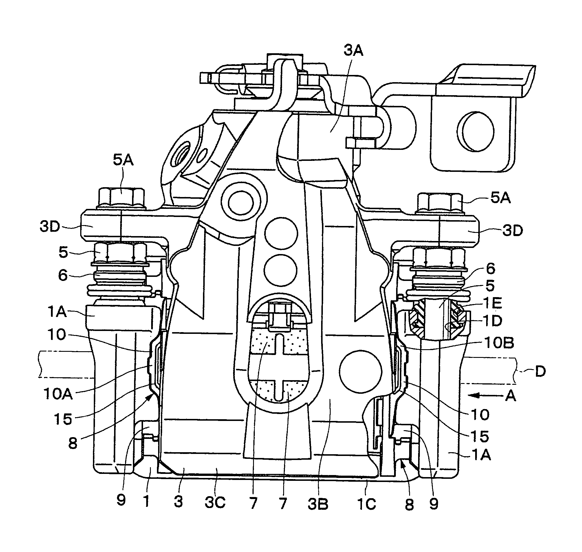
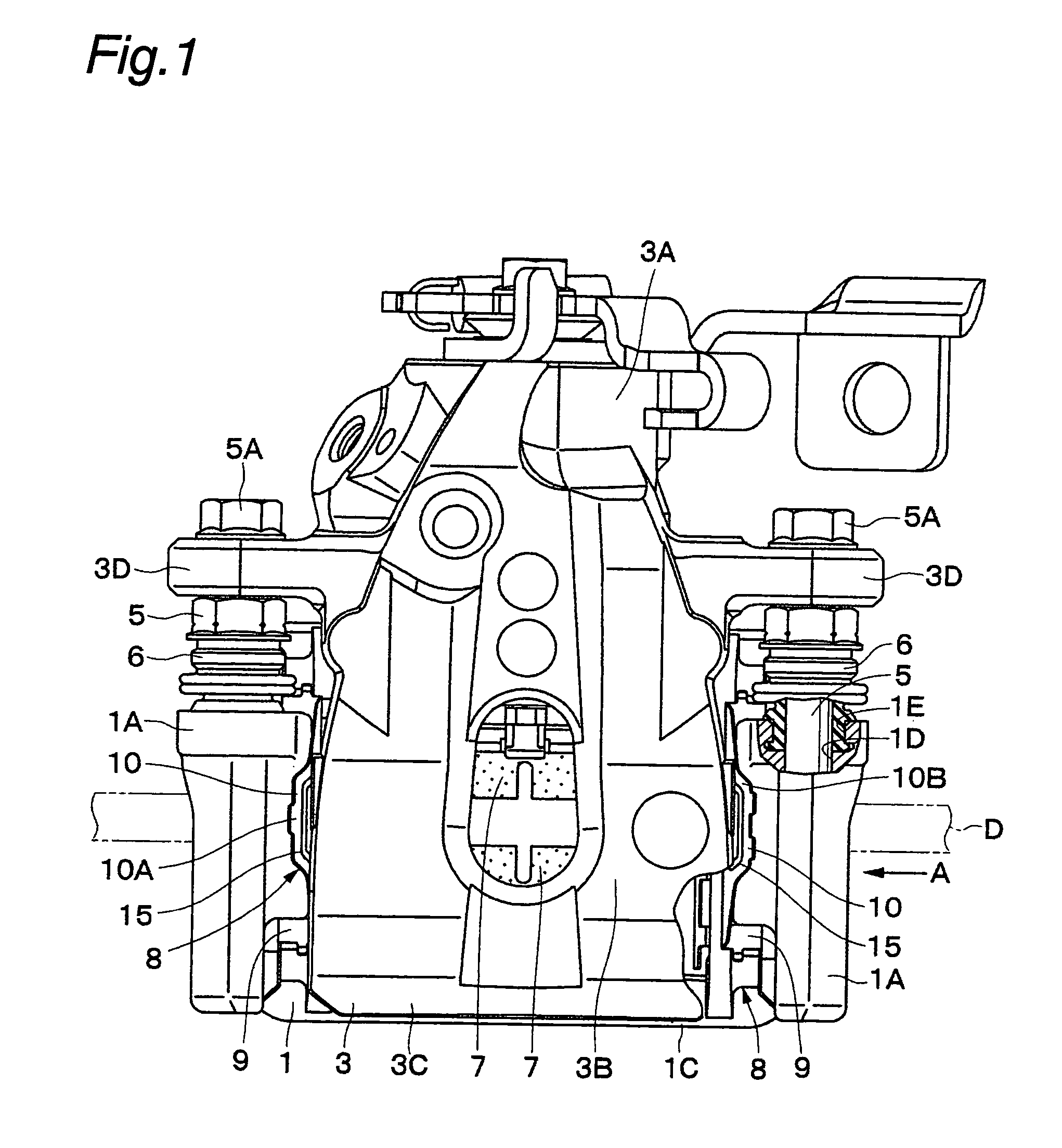
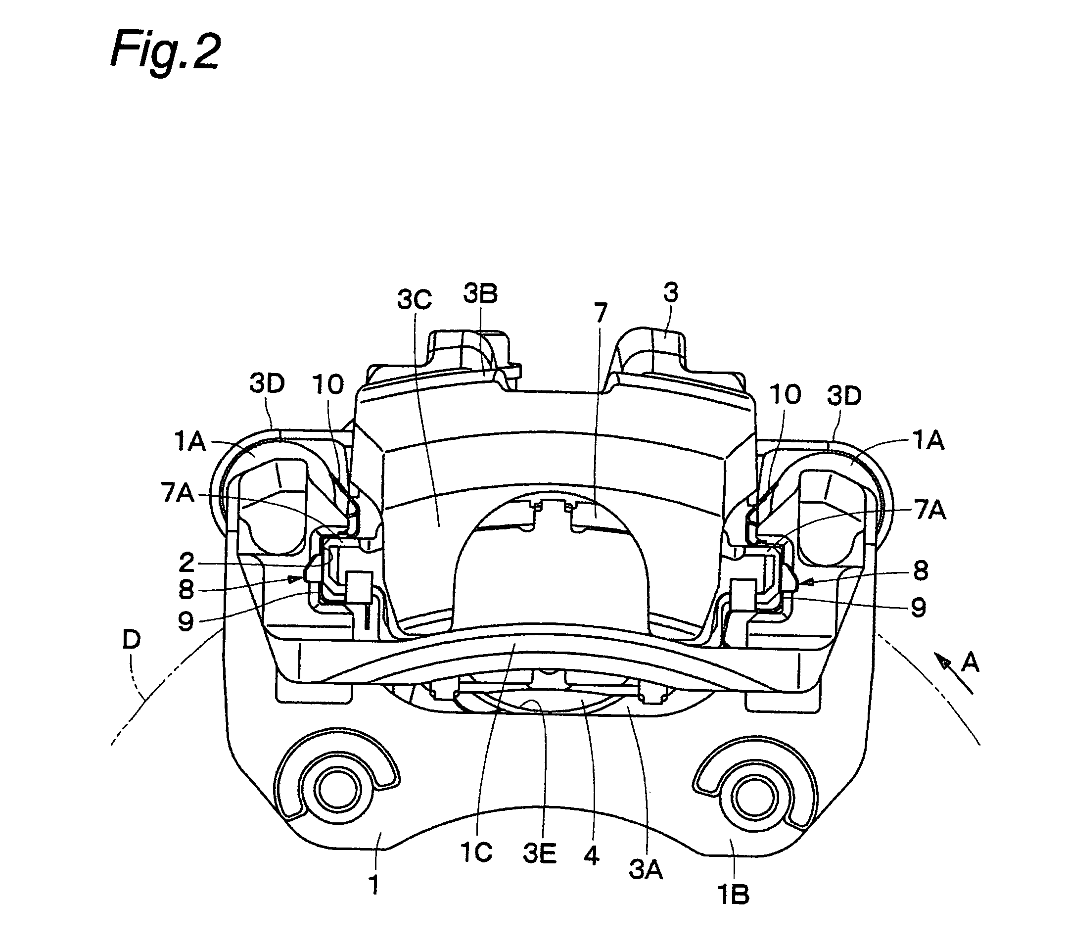
[0035]FIGS. 1 to 8 show the present invention. In this embodiment, a disk brake for use in an automobile will be explained by way of example.
[0036]In the figures, a mounting member 1 is secured to a non-rotating part of a vehicle. As shown in FIGS. 1 and 2, the mounting member 1 is positioned near a disk D that rotates in the direction of the arrow A, together with a wheel (not shown) of the vehicle. In this case, the disk D rotates in the arrow A direction when the vehicle runs in the forward direction.
[0037]The mounting member 1 consists essentially of a pair of arms 1A, 1A, a mounting seat portion 1B, and a bow-shaped reinforcing beam 1C. The arms 1A are spaced apart from each other in the rotational (circumferential) direction of the disk D and extend over the outer periphery of the disk D in the axial direction of the disk D. The mounting seat portion 1B connects together the proximal ends of the arms 1A and is secured to the non-rotating part of the vehicle at the inner side o...
fourth embodiment
[0092]FIGS. 11 to 13 show the present invention. The feature of this embodiment resides in that the present invention is applied to a disk brake of the twin-bore specifications.
[0093]A mounting member 41 is secured to a non-rotating part of a vehicle. The mounting member 41 is arranged substantially in the same way as in the first embodiment. That is, the mounting member 41 has a pair of arms 41A, a mounting seat portion 41B, a reinforcing beam 41C, etc. Each arm 41A has U-groove shaped pad guides 42 positioned at the inner and outer sides, respectively, of a disk D.
[0094]A caliper 43 is slidably provided on the mounting member 41 through sliding pins (not shown). The caliper 43 has an inner leg portion (not shown), a bridge portion 43B, an outer leg portion 43C, mounting portions 43D, etc. substantially in the same way as in the first embodiment. The inner leg portion is provided with two (for example) cylinders, and pistons are slidably fitted in the cylinders, respectively.
[0095]...
fifth embodiment
[0099]FIGS. 14 to 16 show the present invention. The feature of this embodiment resides in that the present invention is applied to a disk brake of specifications different from those described above.
[0100]A mounting member 61 is secured to a non-rotating part of a vehicle. The mounting member 61 is arranged substantially in the same way as in the first embodiment. That is, the mounting member 61 has a pair of arms 61A and a mounting seat portion 61B. Each arm 61A has pad guides 62 positioned at the inner and outer sides, respectively, of a disk D. The pad guides 62 are each formed as an L-shaped stepped portion, for example.
[0101]A caliper 63 is slidably provided on the mounting member 61 through sliding pins (not shown). The caliper 63 has an inner leg portion 63A, a bridge portion 63B, an outer leg portion 63C, mounting portions 63D, a cylinder 63E, etc. substantially in the same way as in the first embodiment. The cylinder 63E has a piston 64 slidably fitted therein.
[0102]Inner ...
PUM
 Abstract
Description
Claims
Application Information
 - R&D
- Intellectual Property
- Life Sciences
- Materials
- Tech Scout
- Unparalleled Data Quality
- Higher Quality Content
- 60% Fewer Hallucinations
Browse by: Latest US Patents, China's latest patents, Technical Efficacy Thesaurus, Application Domain, Technology Topic, Popular Technical Reports.
© 2025 PatSnap. All rights reserved.Legal|Privacy policy|Modern Slavery Act Transparency Statement|Sitemap|About US| Contact US: help@patsnap.com


