Rotor assembly and method of manufacture thereof

a technology of rotating parts and assembly lines, applied in the direction of dynamo-electric machines, electrical apparatus, magnetic circuits, etc., can solve the problems of weakening the connection between the magnet and the shaft, increasing the difficulty of continuous distribution of adhesive along the full length of the bore, and brittleness of most magnets

Inactive Publication Date: 2020-04-30
DYSON TECH LTD
View PDF0 Cites 0 Cited by
  • Summary
  • Abstract
  • Description
  • Claims
  • Application Information

AI Technical Summary

Problems solved by technology

Most magnets are relatively brittle and will fracture if subjected to excessive tensile stress.
Nevertheless, as the length of the magnet increases, it becomes increasingly difficult to achieve a continuous distribution of adhesive along the full length of the bore.
This in turn results in a weaker join between the magnet and the shaft.
However, it is generally difficult to deliver adhesive along the full length of the bore without trapping pockets of air.

Method used


Image

  • Rotor assembly and method of manufacture thereof
  • Rotor assembly and method of manufacture thereof
  • Rotor assembly and method of manufacture thereof

Examples


Embodiment Construction

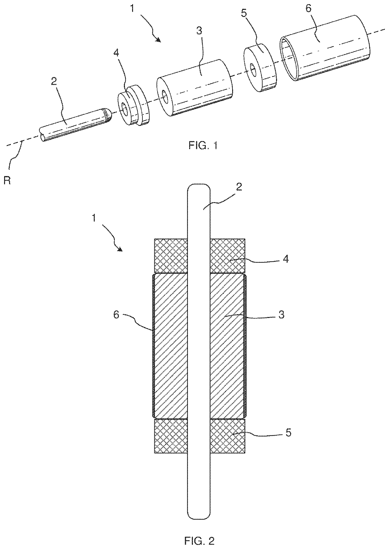
[0028]FIG. 1 shows a rotor assembly 1, and FIG. 2 shows a cross section through a schematic representation of the rotor assembly 1. The rotor assembly comprises a shaft 2 and a magnet 3. The shaft 2 is ceramic, however other materials may be used for the shaft, for example a metal such as steel. The magnet 3 is a permanent magnet. The magnet is formed of a magnetic powder and a binder. The binder is an epoxy. Typically permanent magnets of this sort are formed by compressing the magnetic powder and the binder together and then heating or baking the magnet to cure the binder.

[0029]The rotor assembly further comprises end caps 4 and 5 which are positioned either side of the magnet along the rotational axis R of the rotor assembly. FIG. 1 also shows a protective member in the form of a protective sleeve 6. The protective sleeve 6 is a hollow cylindrical body formed of carbon-fibre composite. Alternative protective members may be used, for example the protective member could be a pre-im...


PUM


Abstract

A method of manufacturing a rotor assembly, the method comprising: providing a magnet in an uncured state comprising a magnetic powder and a binder; providing a shaft onto which the magnet is to be fixed; and assembling an intermediate rotor assembly in which the uncured magnet is positioned on the shaft. The method then comprises heating the intermediate rotor assembly to cure the magnet and to allow a quantity of the binder to leach from the magnet, creating an adhesive bond between the magnet and the shaft.

Description

CROSS-REFERENCE TO RELATED APPLICATIONS[0001]This application is a national stage application under 35 U.S.C. 371 of International Application No. PCT / GB2018 / 051131, filed Apr. 27, 2018, which claims the priority of GB Application No. 1709834.4, filed Jun. 20, 2017, the entire content of each of which are incorporated herein by reference.FIELD OF THE INVENTION[0002]The present invention relates to a rotor assembly suitable for use in an electrical machine and a method of manufacture thereof.BACKGROUND OF THE INVENTION[0003]The rotor of an electrical machine typically comprises a rotor core secured to a shaft. The rotor core may comprise a magnet having a bore through which the shaft is received. Most magnets are relatively brittle and will fracture if subjected to excessive tensile stress. Consequently, rather than press fitting the magnet on to the shaft, the magnet is generally adhered to the shaft.[0004]The magnet may be adhered to the shaft by applying a bead of adhesive to the ...

Claims


Application Information

Patent Timeline
Patent Type & Authority Applications(United States)
IPC IPC(8): H02K1/30H02K1/04H02K1/27H02K7/00H02K7/04H02K15/03H02K15/12
CPCH02K1/04H02K15/03H02K7/003H02K15/12H02K1/2733H02K7/04H02K1/30H02K1/28
Inventor WARNE, DAVID GEORGE
Owner DYSON TECH LTD
Why Eureka
Try Eureka