Dynamic Sensor for Measurement Device

a technology of dynamic sensors and measurement devices, applied in the field of dynamic sensors, can solve the problems the recovery time of the oscillation back to the operating point after a substantial attenuation, and the change of the oscillation frequency of the excited oscillation and in the change of the amplitude of the oscillation, etc., and achieves the effect of reducing the quality factor of the sensing coil, reducing the quality factor, and improving the accuracy of the a measurement device and sensor technology of dynamic sensor and measurement device and dynamic sensor measurement device and dynamic sensor technology, applied in the field of dynamic sensor and measurement device, which is applied in the field of dynamic sensor which is which is too long recovery time the effect of the oscillation time a technology of dynamic sensor and measurement device and sensor field of dynamic sensor technology, applied in the field of dynamic sensor and measurement device and sensor field of dynamic sensor technology, applied in the field of dynamic sensor and measurement device and dynamic sensor technology, applied in th

Active Publication Date: 2020-04-30
PEPPERL & FUCHS SE
View PDF3 Cites 1 Cited by
  • Summary
  • Abstract
  • Description
  • Claims
  • Application Information

AI Technical Summary

Benefits of technology

[0024]A further advantage of the oscillating sensor device is that the oscillating sensor device automatically adjusts to the specific use case so that in the application field, no further adjustment is necessary.

Problems solved by technology

Further, the presence of an object in the sensing range leads to a decrease of a quality factor of the sensing coil caused by an energy loss due to the production of eddy currents in the object.
In operation this results in a change of oscillation frequency of the excited oscillation and in a change of the amplitude of oscillation.
However, if the open loop gain characteristics of the oscillator is too flat (constant amplification), the recovery time to bring the oscillation back to the operating point after a substantial attenuation, may be too long for a given application.
Also, in case of loop gain characteristics with a too flat amplification, there might be no fixed operating point for unattenuated condition so that in steady state operation no stable operating point is reached.
However, using semiconductor effects for forming the gain characteristics introduces a high temperature dependency and suffer from a low reproducibility so that the application in inductive sensors, such as proximity sensors, is not appropriate.
Furthermore, those non-linear gain characteristics based on semiconductor effects cannot be easily tuned.

Method used


Image

  • Dynamic Sensor for Measurement Device
  • Dynamic Sensor for Measurement Device
  • Dynamic Sensor for Measurement Device

Examples


Embodiment Construction

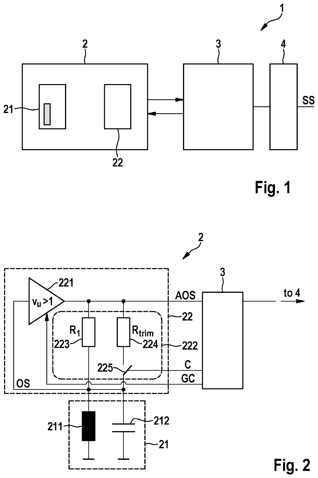
[0045]FIG. 1 schematically shows a measurement device 1 with an oscillating sensor device 2. In the present embodiment the oscillating sensor device 2 may be part of a proximity sensor for detecting the entering of a conductive object into a sensing range of the oscillating sensor device 2. In the following, the invention is described in the context of a proximity sensor. However, the inventive ideas can be applied to any measurement devices using oscillating sensors by which changes of a physical situation shall be detected.

[0046]The oscillating sensor 2 has a resonance circuit 21 and an amplifier 22. The resonance circuit 21 has an inductor 211 which may be provided as a sensing coil. In operation, the resonance circuit 21 oscillates and generates an alternating magnetic field in a sensing range around the sensing coil. The alternating magnetic field is affected by any conductive objects being present or moving through the sensing range. This is caused by eddy currents which are i...


PUM


Abstract

An oscillating sensor device, particularly for a proximity sensor, for sensing a dynamic change of attenuation caused by a measurable physical effect includes an oscillator including a resonance circuit and an amplifier fed back to the resonance circuit and configured to maintain oscillation of the oscillator, and a control unit configured to control the open loop gain of the oscillator. The amplifier comprises a non-linear gain characteristics defining an operating point at a preset amplitude of oscillation. The control unit is configured to control the open loop gain of the oscillator so that the operating point is set to a preset amplitude of the oscillation.

Description

CROSS-REFERENCE TO RELATED APPLICATIONS[0001]This application claims the priority, under 35 U.S.C. § 119(a)-(d), to German Patent Application No. 10 2018 126 648.0, filed Oct. 25, 2018; the prior applications are herewith incorporated by reference in their entirety.STATEMENT REGARDING FEDERALLY SPONSORED RESEARCH OR DEVELOPMENT[0002]Not ApplicableFIELD OF THE INVENTION[0003]The present invention relates to dynamic sensors having an oscillator with a resonance circuit and an amplifier with a controllable loop gain. Particularly, the present invention relates to measures to increase sensitivity of the dynamic sensor in a reproducible manner.BACKGROUND OF THE INVENTION[0004]Dynamic sensors are generally used to detect a change of state caused by various physical effects. One example of dynamic sensors are inductive sensors wherein a change of impedance of a sensing coil in an oscillator can be detected by sensing a change of amplitude of a resulting oscillation. Particularly, such indu...

Claims


Application Information

Patent Timeline
Patent Type & Authority Applications(United States)
IPC IPC(8): H03K17/95
CPCH03K17/955H03K17/9547G01D5/20G01V3/102H03B5/12H03K17/9535H03K17/9532H03K17/9502H03K2217/9401
Inventor KÜHN, THOMASVATER, JOCHENBRAUNSMANN, CHRISTOPH
Owner PEPPERL & FUCHS SE
Why Eureka
Try Eureka