Micro channel structure

a micro channel and structure technology, applied in the direction of positive displacement liquid engines, laboratory glassware, liquid fuel engines, etc., can solve the problems that the conventional miniaturized fluid transporting structure cannot be implanted to transport gas, and achieve the stability of the structural size and flatness of the micro channel structure of the present disclosure, and the reliability and service life of the operation increase.

Active Publication Date: 2020-05-07
MICROJET TECH
View PDF0 Cites 7 Cited by
  • Summary
  • Abstract
  • Description
  • Claims
  • Application Information

AI Technical Summary

Benefits of technology

[0005]The object of the present disclosure is to provide a micro channel structure. The micro channel structure of the present disclosure is driven by electric energy and capable of transporting gas. Since the micro channel structure of the present disclosure is produced by a standard ...

Problems solved by technology

It is obviously that the conventional fluid transportation devices gradually tend to miniaturize the structure and maximize the flow rate thereof.
Ho...

Method used


Image

  • Micro channel structure
  • Micro channel structure
  • Micro channel structure

Examples


Embodiment Construction

[0015]The present disclosure will now be described more specifically with reference to the following embodiments. It is to be noted that the following descriptions of preferred embodiments of this disclosure are presented herein for purpose of illustration and description only. It is not intended to be exhaustive or to be limited to the precise form disclosed.

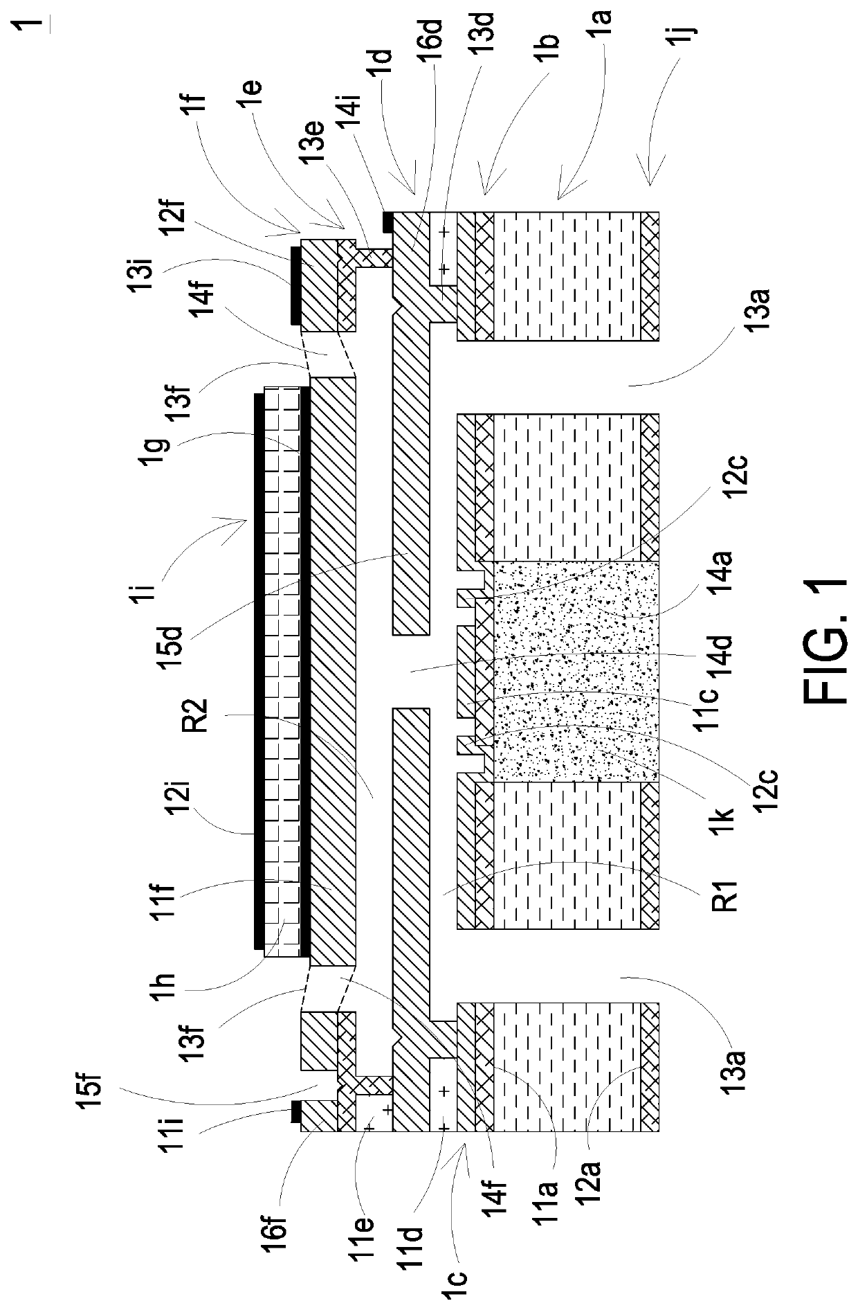
[0016]Please refer to FIG. 1. The present disclosure provides a micro channel structure 1 including at least one substrate 1a, at least one first surface 11a, at least one second surface 12a, at least one receiving slot 14a, at least one first insulation layer 1b, at least one supporting layer 1c, at least one protruding part 11c, at least one conductive part 12c, at least one valve layer 1d, at least one base part 13d with a height, at least one movable part 15d, at least one fixed part 16d, at least one hollow aperture 14d, at least one first chamber R1, at least one second insulation layer 1e, at least one supporting part 13...


PUM


Abstract

A micro channel structure includes a substrate, a supporting layer, a valve layer, a second insulation layer, a vibration layer and a bonding-pad layer. A flow channel is formed on the substrate. A conductive part and a movable part are formed on the supporting layer and the valve layer, respectively. A first chamber is formed at the interior of a base part and communicates to the hollow aperture. A supporting part is formed on the second insulation layer. A second chamber is formed at the interior of the supporting layer and communicates to the first chamber through the hollow aperture. A suspension part is formed on the vibration layer. By providing driving power sources having different phases to the bonding-pad layer, the suspension part moves upwardly and downwardly, and a relative displacement is generated between the movable part and the conductive part, to achieve fluid transportation.

Description

FIELD OF THE DISCLOSURE[0001]The present disclosure relates to a micro channel structure, and more particularly to a micro channel structure driven by electric energy.BACKGROUND OF THE DISCLOSURE[0002]Currently, in all fields, the products used in many sectors such as pharmaceutical industries, computer techniques, printing industries or energy industries are developed toward elaboration and miniaturization. The fluid transportation devices are important components that are used in for example micro pumps, micro atomizers, printheads or the industrial printers.[0003]With the rapid advancement of science and technology, the application of fluid transportation device tends to be more and more diversified. For the industrial applications, the biomedical applications, the healthcare, the electronic cooling and so on, even the most popular wearable devices, the fluid transportation device is utilized therein. It is obviously that the conventional fluid transportation devices gradually te...

Claims


Application Information

Patent Timeline
IPC IPC(8): B01L3/00
CPCB01L3/502707B81B2203/0338B32B2307/202B01L2300/0887B01L3/502738B01L3/502715B32B2307/206F04B43/043F04B53/1072F16K99/0015F16K99/0051F16K99/0048F16K2099/0074F16K2099/008F04B45/047F04B43/046
Inventor MOU, HAO-JANYU, RONG-HOCHANG, CHENG-MINGTAI, HSIEN-CHUNGLIAO, WEN-HSIUNGHUANG, CHI-FENGHAN, YUNG-LUNGKUO, CHUN-YI
Owner MICROJET TECH
Why Eureka
Try Eureka