Body structure for a vehicle

a vehicle and body technology, applied in the field of vehicle body structures, can solve the problems of affecting the collision performance, affecting the stability of the reinforcement element facing the collision, etc., and achieve the effects of increasing the rigidity of the component, increasing the pressure stability and bending stability

Active Publication Date: 2020-05-07
VOLKSWAGEN AG
View PDF0 Cites 4 Cited by
  • Summary
  • Abstract
  • Description
  • Claims
  • Application Information

AI Technical Summary

Benefits of technology

[0019]To further increase the component rigidity, the middle portion of the jacking point sheet metal part may have at least one longitudinal ridge. The longitudinal ridge may protrude from a middle portion base surface with a predefined ridge height, in the vehicle transverse direction. The longitudinal ridge may preferably extend directly to the stop edge of the middle portion. In this way, the stop base provided by the stop edge may be elevated in the vehicle transverse direction.
[0020]For the case of a double-wall design of the middle portion, it is particularly preferred when the longitudinal ridge is formed in one sheet metal layer (for example, the outer sheet metal layer in the vehicle transverse direction), and the other sheet metal layer (for example, the inner sheet metal layer in the vehicle transverse direction) is designed as a cover part that covers a hollow profile of the longitudinal ridge. This results in a closed ridge hollow profile having a rigid design.
[0021]The upper and lower joining flanges, preferably together with the longitudinal ridge, may all be formed in one of the two sheet metal layers. Alternatively and / or additionally, the upper and / or lower joining flange(s) may extend to the level of the stop edge of the middle portion in the vehicle longitudinal direction. In this case, the stop edge may extend, without steps or interruptions, from the middle portion to the upper and / or lower joining flange. A joining flange that is extended in this way in the vehicle longitudinal direction brings about an increase in the pressure stability and bending stability, and provides an additional connection surface on the door sill.

Problems solved by technology

With the upper door sill design, there is a risk, in particular in a head-on collision with little lateral overlap, that the reinforcement element facing the collision may be acted on by a collision force directed toward the rear of the vehicle.
If the connecting points between the reinforcement element and the door sill rupture in this case, the reinforcement element may longitudinally shift with respect to the door sill, which has an adverse effect on the collision performance.

Method used


Image

  • Body structure for a vehicle
  • Body structure for a vehicle
  • Body structure for a vehicle

Examples


Embodiment Construction

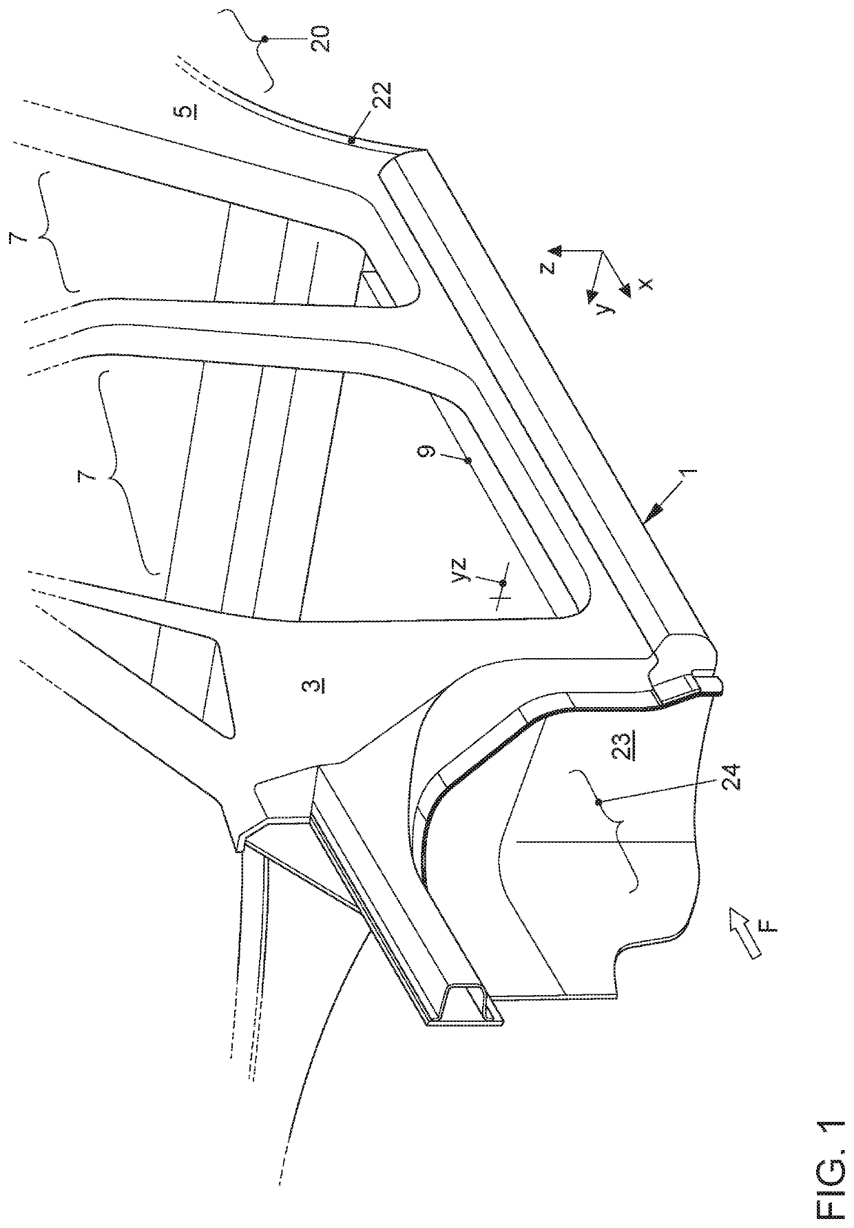
[0030]FIG. 1 shows a body structure of a two-track motor vehicle, which is described below to the extent necessary for an understanding of the invention. Accordingly, the body structure has a floor-side door sill 1 on each side in the transverse direction y, only one door sill being shown in FIG. 1. The door sill 1 extends continuously in the vehicle longitudinal direction x, between a front A-pillar 3 and a rear C-pillar 5, and delimits side door openings 7 on the floor side. A traction battery 9 that is vulnerable in a collision extends between the two door sills 1 in the vehicle transverse direction y, and is installed in the vehicle floor of the body structure.

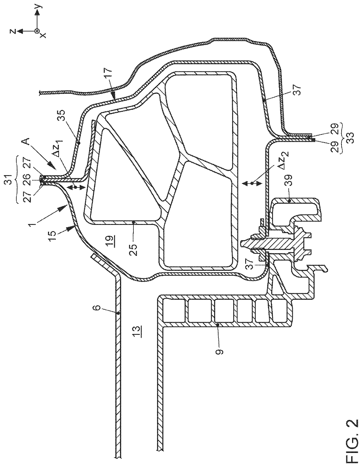
[0031]The door sill 1 in FIG. 2 is designed as a hollow beam, in particular with a door sill inner part 15 on the inner side of the vehicle, in the vehicle transverse direction y, and a door sill outer part 17 on the outer side of the vehicle, in the vehicle transverse direction y. These door sill inner and outer parts del...


PUM


Abstract

A body structure for a vehicle has at least one side door sill that is made up of a door sill outer part on the outer side of the vehicle and a door sill inner part on the inner side of the vehicle, in the vehicle transverse direction, which delimit a door sill cavity that extends in the vehicle longitudinal direction between a front closing profile that closes off the door sill cavity in the direction of the front wheel housing, and a rear closing profile that closes off the door sill cavity in the direction of the rear wheel housing, wherein a reinforcement element, designed as an insert part, which extends in the vehicle longitudinal direction and acts as a side collision reinforcement is situated in the door sill cavity, and wherein in the event of a head-on collision the reinforcement element is acted on by a collision force directed toward the rear of the vehicle, in particular with load on at least one connecting point at which the reinforcement element is connected to the door sill. According to the invention, to relieve load on the connecting point, the reinforcement element is spaced apart from the rear closing profile by a longitudinal clearance space. A jacking point sheet metal part extends in the vertical vehicle direction, transversely through the longitudinal clearance space, and, in a head-on collision, the jacking point sheet metal part acts as a longitudinal stop by means of which longitudinal shifting of the reinforcement element is prevented.

Description

FIELD OF THE INVENTION[0001]The invention relates to a body structure for a vehicle.BACKGROUND OF THE INVENTION[0002]In an electrically operated two-track vehicle, a traction battery may be installed in the vehicle floor, extending in the vehicle transverse direction between the side door sills of the vehicle which delimit the side door openings of the vehicle body on the floor side. The traction battery installed in the vehicle floor, as a functional element that is vulnerable in a collision, must be protected from damage, in particular in a side pole collision.[0003]In a generic body structure, the side door sill is made up a door sill outer part on the outer side of the vehicle and a door sill inner part on the inner side of the vehicle in the vehicle transverse direction, which delimit a door sill cavity. The door sill cavity extends in the vehicle longitudinal direction between a front closing profile that closes off the door sill cavity in the direction of the front wheel hous...

Claims


Application Information

Patent Timeline
Patent Type & Authority Applications(United States)
IPC IPC(8): B62D21/15B62D25/02
CPCB62D29/008B62D25/025B62D21/157B62D25/2036B62D25/00B62D27/065B62D27/02B60K2001/0438B60Y2306/01
Inventor SCHUPPERT, EIKEVAN DE WIEL, JOHANNESUBALDO, MARIOKRENGEL, SÖRENWEINGARTEN, UWE
Owner VOLKSWAGEN AG
Why Eureka
Try Eureka