
Capacitor device for a conductor loop in a device for the in-sity production of heavy oil and bitumen from oil-sand deposits

a technology of conductor loop and capacitor, which is applied in the direction of capacitor manufacturing, insulation, borehole/well accessories, etc., can solve the problems of relatively high voltage drop, high degree of complexity in respect of pressure loss occurring during introduction of gases/vapors, and complex manner, so as to achieve flexibility or capacity for tensile loading and increase thermal resistance. , the effect of increasing the mechanical stability

Inactive Publication Date: 2017-01-31
SIEMENS AG
View PDF12 Cites 0 Cited by
  • Summary
  • Abstract
  • Description
  • Claims
  • Application Information

AI Technical Summary

Benefits of technology

[0009]The object of the embodiments includes at least partially elevating the above-described disadvantages in the case of devices for the production of heavy oil and bitumen from oil sands deposits. In particular, the object of the embodiments includes providing a capacitor device for a conductor loop of a device for the “in situ” production of heavy oil and bitumen from oil sands deposits, a corresponding conductor loop and a method for producing the conductor loop. In these embodiments, the device, conductor loop, and method are capable of providing, in a cost-effective and simple manner, the desired resistance to tensile stresses and bending stresses and high levels of dielectric strength or resistance to partial discharges of the capacitor.
[0043]The following advantages may result in, inter alia, one or more of the following, (1) High dielectric strengths or resistances to partial discharges at simultaneously high temperatures of the capacitors with ceramic (or glass film, mica) dielectrics may be achieved. (2) Flexibility is predominantly achieved by the more flexible connecting lines, where the electrical requirements for the outer insulation are reduced. This largely enables a rigid design of the capacitors, which, for the first time, enables the use of ceramics. (3) Suitable dimensioning allows connecting lines with a length below 20 m, for which transport is easily possible. Thus, conductor loops with large total lengths (1-3 km) may also be realized since assembly does not need to take place until at the bore hole. (4) Acceptance tests with respect to mechanical and electrical requirements may be performed for each capacitor and each connecting line independently in suitable test chambers (e.g., furnaces with partial discharge measurement devices) prior to integration in the entire system. (5) Replacement of defective capacitors or connecting lines is possible (after drawing of the inductor). (6) Production of the components of a conductor loop may be performed simultaneously at different production sites.

Problems solved by technology

This is associated with the disadvantage that it is necessary to provide the possibility, in a very complex manner, of transporting the gases into the desired position in the ground, namely to the deposit location of the oil sands.
Furthermore, owing to sometimes very deep and extensive deposits, a high degree of complexity in respect of the pressure loss occurring during introduction of the gases / vapors needs to be considered.
Owing to the long length of such a conductor loop that may be up to several kilometers, however, there is the problem that relatively high voltage drops are produced by the voltages induced in the surrounding ground.
These high voltage drops result in immense costs and complexities in terms of the device for operating such a conductor loop.
One disadvantage with the above-described solution is that the distributed capacitor arrangement represents a restriction in terms of the mechanical properties of the conductor loop itself.
Furthermore, the use possibilities for a wide variety of materials for the dielectric materials of the individual capacitors are restricted since the materials likewise need to withstand the corresponding bending stresses and tensile stresses.
Furthermore, this results in larger cable thicknesses or poorer compensation performances.

Method used


Image

  • Capacitor device for a conductor loop in a device for the in-sity production of heavy oil and bitumen from oil-sand deposits
  • Capacitor device for a conductor loop in a device for the in-sity production of heavy oil and bitumen from oil-sand deposits
  • Capacitor device for a conductor loop in a device for the in-sity production of heavy oil and bitumen from oil-sand deposits

Examples


Embodiment Construction

[0055]Elements having the same function and mode of operation have been provided in each case with the same reference symbols in FIGS. 1 to 8.

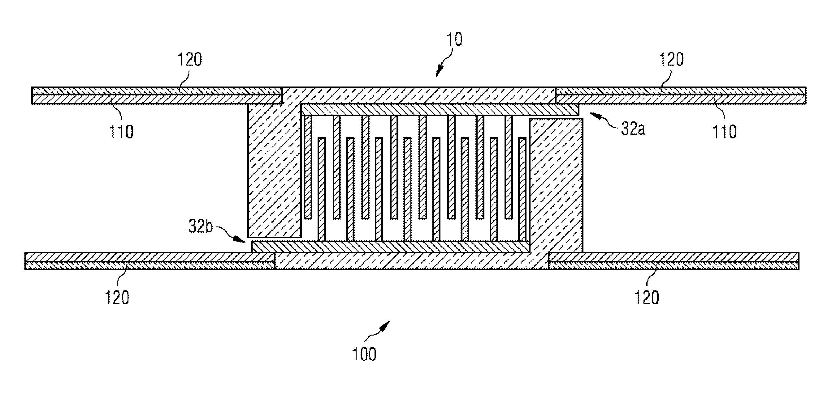
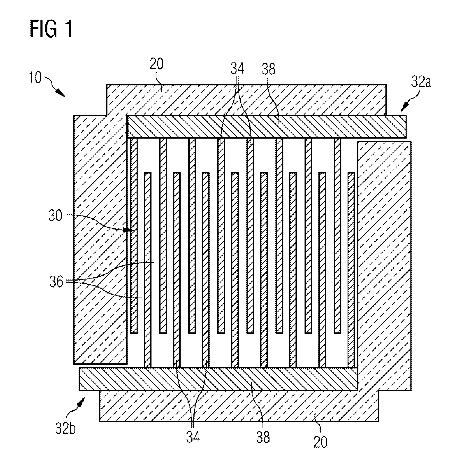
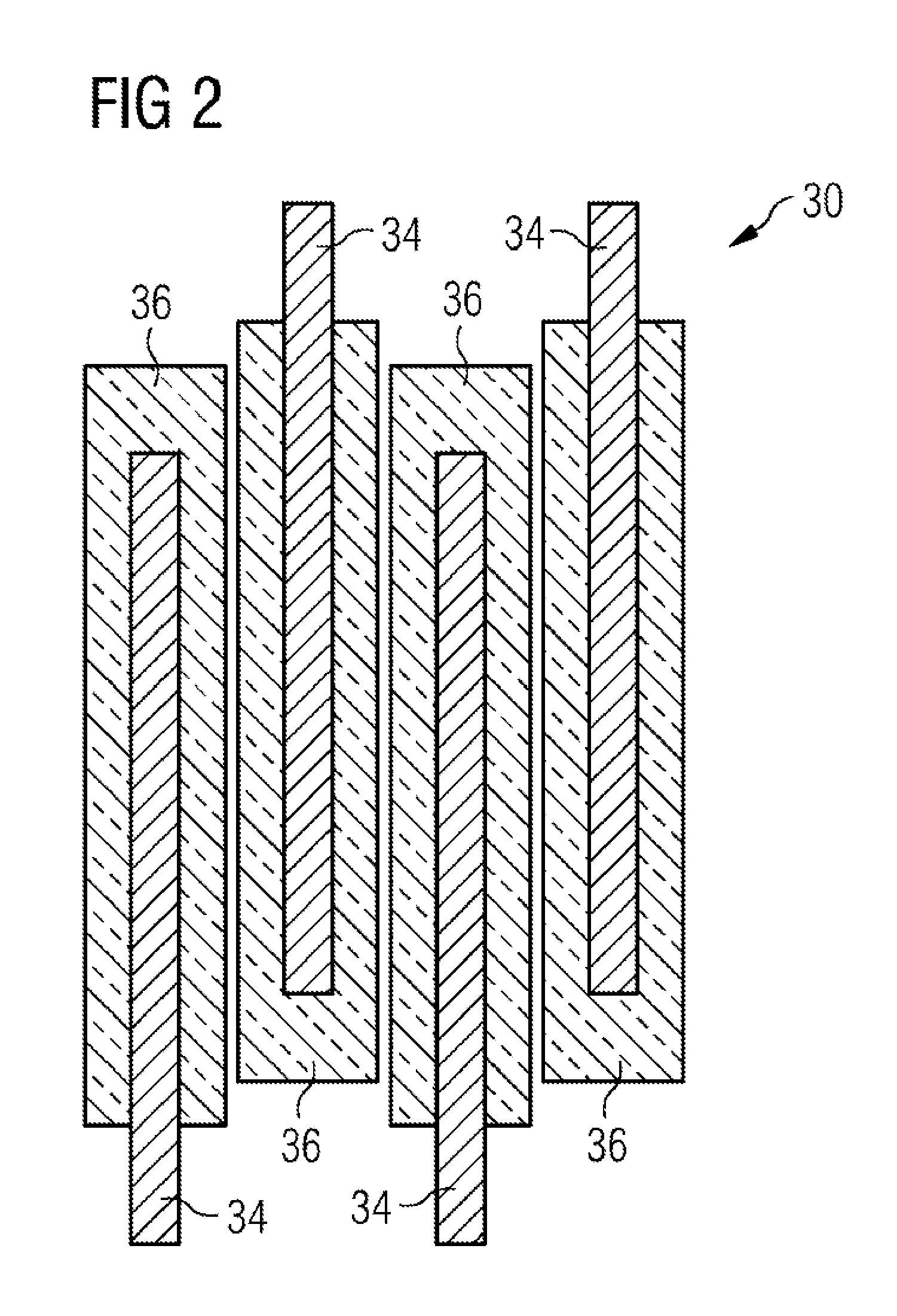
[0056]FIG. 1 depicts a first embodiment of a capacitor device 10. The capacitor device is provided with a housing 20, which may have an electrically insulating effect. A capacitor unit 30 is arranged in the interior of this housing 20. The capacitor unit has a multiplicity of opposite capacitor plates 34, where each plate may be referred to as a capacitor plate stack. The capacitor plates 34 are all carried by a plate carrier 38. The respective plate carrier 38 at the same time forms, at least partially, the connection interfaces 32a and 32b. Mechanical and electrically conductive contact is made with line elements 110 connected there later at these connection interfaces 32a and 32b.

[0057]The assembled variant is depicted, for example, in FIG. 3. In FIG. 3, a line element 110 is attached to the respective connection interface 32a and 32b in t...


PUM

PropertyMeasurementUnit
frequencyaaaaaaaaaa
thicknessaaaaaaaaaa
thicknessaaaaaaaaaa

Abstract

The embodiments relate to a capacitor device for a conductor loop in a device for the in-situ production of heavy oil and bitumen from oil-sand deposits, characterized by a housing and a capacitor unit arranged therein to compensate for the inductive voltage drop along the conductor loop, wherein there are two connection interfaces, wherein each connection interface is designed for mechanical and electrically conductive connection between the capacitor unit and a conductor element of the conductor loop.

Description

CROSS-REFERENCE TO RELATED APPLICATIONS[0001]The present patent document is a §371 nationalization of PCT Application Serial Number PCT / EP2012 / 070560, filed Oct. 17, 2012, designating the United States, which is hereby incorporated by reference, and this patent document also claims the benefit of EP 11186890.7, filed Oct. 27, 2011, and EP 12154736.8, filed Feb. 9, 2012, which are also hereby incorporated by reference.TECHNICAL FIELD[0002]The embodiments relate to a capacitor device for a conductor loop of a device for the “in situ” production of heavy oil and bitumen from oil sands deposits, to a conductor loop including a multiplicity of conductor elements and a capacitor device, and to a method for producing a conductor loop.BACKGROUND[0003]It is known that, for the production of oil, it is also possible to use oil deposits in which the oil needs to be separated from the sand in a separation process. In deposits in which the oil sands are not accessible using open-pit mining, howe...

Claims


Application Information

Patent Timeline
Patent Type & Authority Patents(United States)
IPC IPC(8): H01G4/30H01G4/224H01G13/00H01G4/018H01G4/04H01G4/228H01G4/38E21B36/04H01G4/40E21B43/24
CPCH01G4/30E21B36/04E21B43/24E21B43/2401H01G4/018H01G4/04H01G4/224H01G4/228H01G4/38H01G4/40H01G13/00Y10T29/43
Inventor DIEHL, DIRKKOCH, ANDREAS
Owner SIEMENS AG
Learn More