Gradient system for an NMR tomograph

a gradient system and nuclear spin resonance technology, applied in the field of gradient system for nuclear spin resonance tomographs, can solve the problems of complex asymmetric system construction, lack of transverse access possibility, and blockage of access, and achieve high linearity of the generated gradient field, simple manufacturing procedure, and high performance capability

Inactive Publication Date: 2000-09-26
BRUKER ANALYTISCHE MESSTECHN
View PDF14 Cites 4 Cited by
  • Summary
  • Abstract
  • Description
  • Claims
  • Application Information

AI Technical Summary

Benefits of technology

The present invention seeks to provide a gradient system for an NMR tomograph, which on the one hand enables a comfortable axial and transverse access to the measuring volume with a constructional size as small as possible and with a simple manufacturing procedure, and which on the other hand has a high performance capability with respect to the gradient strength produced for given ampere turns, a high linearity of the generated gradient fields, and low inductance and electrical resistance of the conductor segments.
Finally, in an embodiment of the gradient system of the invention which is particularly preferred, the partial gradient systems comprise one-sided recesses perpendicular to the z-axis in the range of central plane E, which recesses extend only across a part of the azimuthal angle range around the z-axis. By means of the coil parts of the gradient system which are in the immediate neighborhood of the measuring volume, a considerably higher gradient strength for equal current through the coils is reached. In this way, the efficiency of the gradient system of the invention can be increased even further. In further simplified embodiments, it is thereby even possible, to realize the gradient system of the invention without any axial mobility of the partial gradient systems along the z-axis, whereby the above presented aim of the invention is nevertheless completely and adequately achieved. This is possible since for whole body examinations of patients in an NMR tomograph, the bottom of the construction need not comprise a possibility of free transverse access, since the patient rests anyway on a continuous patient bed. It is therefore perfectly sufficient to provide for a one-sided recess of the gradient coils on both sides of the central plane E in the upper azimuthal angular range. If this recess is formed with a sufficient axial length parallel to the z-axis, the entire gradient system can also easily be designed rigid and joined together at the bottom across the central plane E. In this way, the costly mechanisms for shifting the partial gradient systems can be saved, whereby an operator keeps nevertheless an optimum free access to the measuring volume from above and from the side.

Problems solved by technology

However, in conventional NMR systems, this access is blocked, in particular in the transverse direction, inter alia by the gradient coil system.
However, the very complicated asymmetric construction of the system and the lack of transverse access possibility are a disadvantage.
The gradient coil system known from WO 91 / 17454, where the gradient coils as a whole can be shifted inside a C-magnet, too, does not enable transverse access to the measuring volume.
However, no free transverse access to the measuring volume which could be used by a surgeon is present in this system.
Compared to gradient coil systems which are merely located on a single cylinder surface, such gradient systems have, however, a larger inductance and a lower efficiency, and as a consequence, for identical ampere turns a lower gradient strength inside the measuring volume is reached.
Finally, the particular arrangement of the gradient coil segments on different radii requires a relatively complicated winding procedure and a considerably larger radial extension of the completed gradient systems.

Method used


Image

  • Gradient system for an NMR tomograph
  • Gradient system for an NMR tomograph
  • Gradient system for an NMR tomograph

Examples


Embodiment Construction

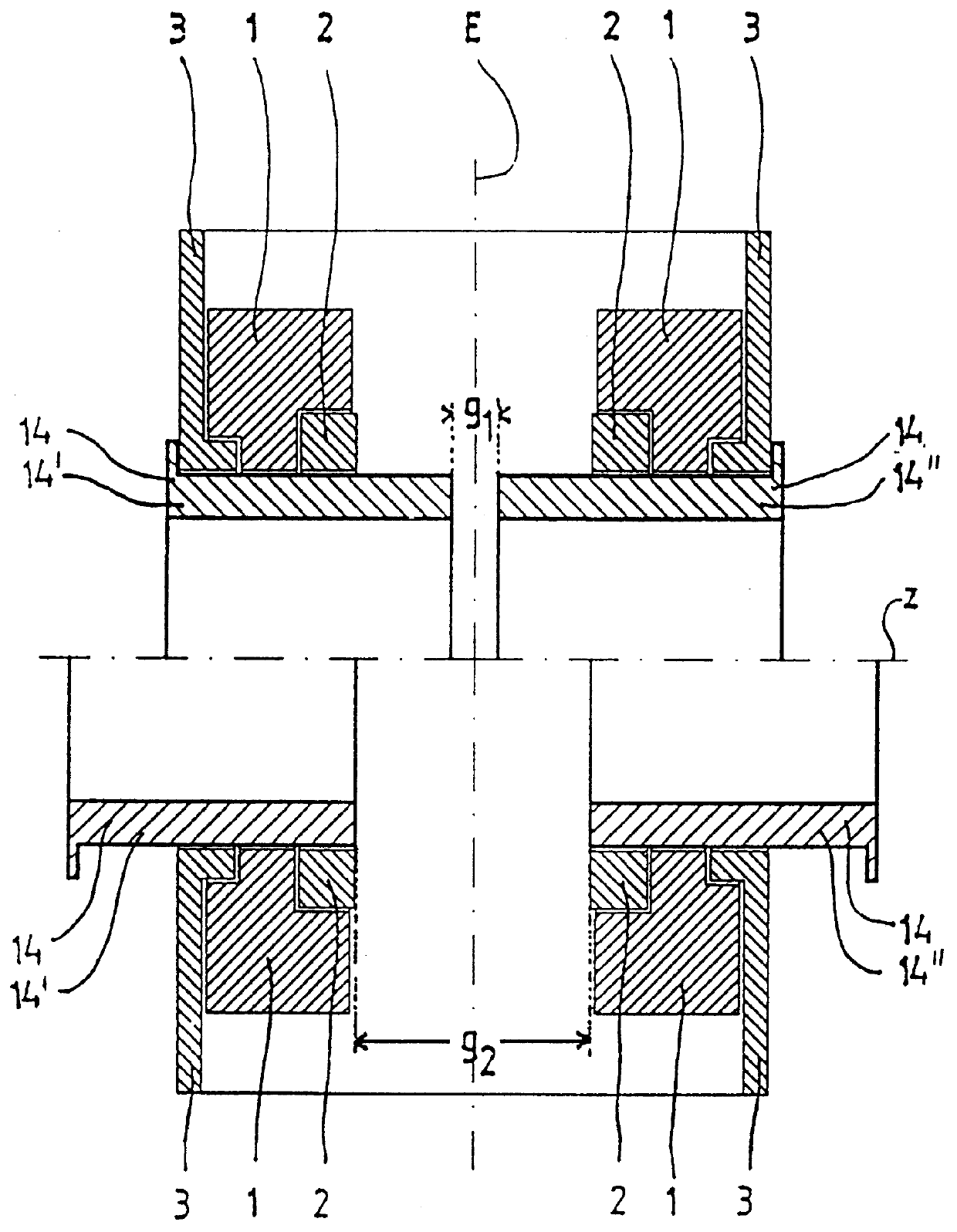
FIG. 1 shows a schematic horizontal cross section through an NMR tomograph with a main magnet system consisting of a magnet coil 1, a ferromagnetic ring 2 to homogenize the magnetic field generated inside the measuring volume as well as an iron shield 3. Radially inside the main magnet system, a gradient system 14 for the generation of a field gradient being as linear as possible in three spatial directions inside the measuring volume is located and can be shifted along the common z-axis. In the embodiment shown, gradient system 14 consists of two partial gradient systems 14', 14", which are located at opposite sides of a central plane E across the measuring volume which plane is perpendicular to the z-axis. In an advantageous way, the gradient system 14, as well as the main magnet system 1, 2, 3, also, are mirror symmetrical with respect to central plane E. For particular cases of use, it may, however, be preferred to choose asymmetric configurations.

In the upper part of FIG. 1, th...


PUM


Abstract

A gradient system for a nuclear spin resonance (NMR) tomograph with a main magnet system producing a homogeneous magnetic field directed along a z-axis inside a measuring volume, wherein the main magnet system provides access to the measuring volume along the z-axis and transversely to the z-axis, and wherein the gradient system comprises two first partial gradient systems which are located at opposite sides of a central plane perpendicular to the z-axis, across the measuring volume. At least one of the two partial gradient systems is movable between at least two positions along the z-axis. In this way, with a small constructional size and with a simple manufacturing procedure, a gradient system is obtained with high performance capability with respect to generated gradient strength for given ampere turns, high linearity of the generated gradient fields, minimum inductance and minimum electrical resistance of the conductor segments.

Description

FIELD OF THE INVENTIONThe invention concerns a gradient system for a nuclear spin resonance (NMR) tomograph with a main magnet system, producing a homogeneous magnetic field directed along a z-axis inside a measuring volume, in which the main magnet system provides access to the measuring volume transverse to the z-axis, and in which the gradient system comprises two first partial gradient systems which are located at opposite sides of a central plane across the measuring volume which central plane is perpendicular to the z-axis.Such a gradient system is known from U.S. Pat. No. 5,414,360.BACKGROUND OF THE INVENTIONNMR tomographs for imaging investigation methods comprise as essential components besides the main magnet a gradient coil system, generally consisting of three gradient coils which can, independently of each other, be supplied with currents of different strengths.In this way, preferably linear, constant magnetic field gradients with adjustable strengths can be added to th...

Claims


Application Information

Patent Timeline
Patent Type & Authority Patents(United States)
IPC IPC(8): G01V3/00G01R33/385
CPCG01R33/385
Inventor MULLER, WOLFGANG
Owner BRUKER ANALYTISCHE MESSTECHN
Why Eureka
Try Eureka