Energy storage systems and methods for fault mitigation

a technology of energy storage and fault mitigation, applied in the field of electric systems, can solve the problems of relative high short-circuit current, increasing costs, and components achieving such current handling may be infeasibl

Inactive Publication Date: 2020-05-07
S&C ELECTRIC
View PDF0 Cites 6 Cited by
  • Summary
  • Abstract
  • Description
  • Claims
  • Application Information

AI Technical Summary

Problems solved by technology

Lithium ion batteries are commonly utilized due to their availability and relatively low costs; however, their relatively low impedance can result in relatively high short-circuit currents in the event of a fault.
This increases the potential amount of short-circuit current within the energy storage system, which, in turn, increases the maximum current handling capabilities required for fuses, switches, and other circuitry components, thereby increasing costs, and in some instances, components achieving such current handling may be infeasible.

Method used


Image

  • Energy storage systems and methods for fault mitigation
  • Energy storage systems and methods for fault mitigation
  • Energy storage systems and methods for fault mitigation

Examples


Embodiment Construction

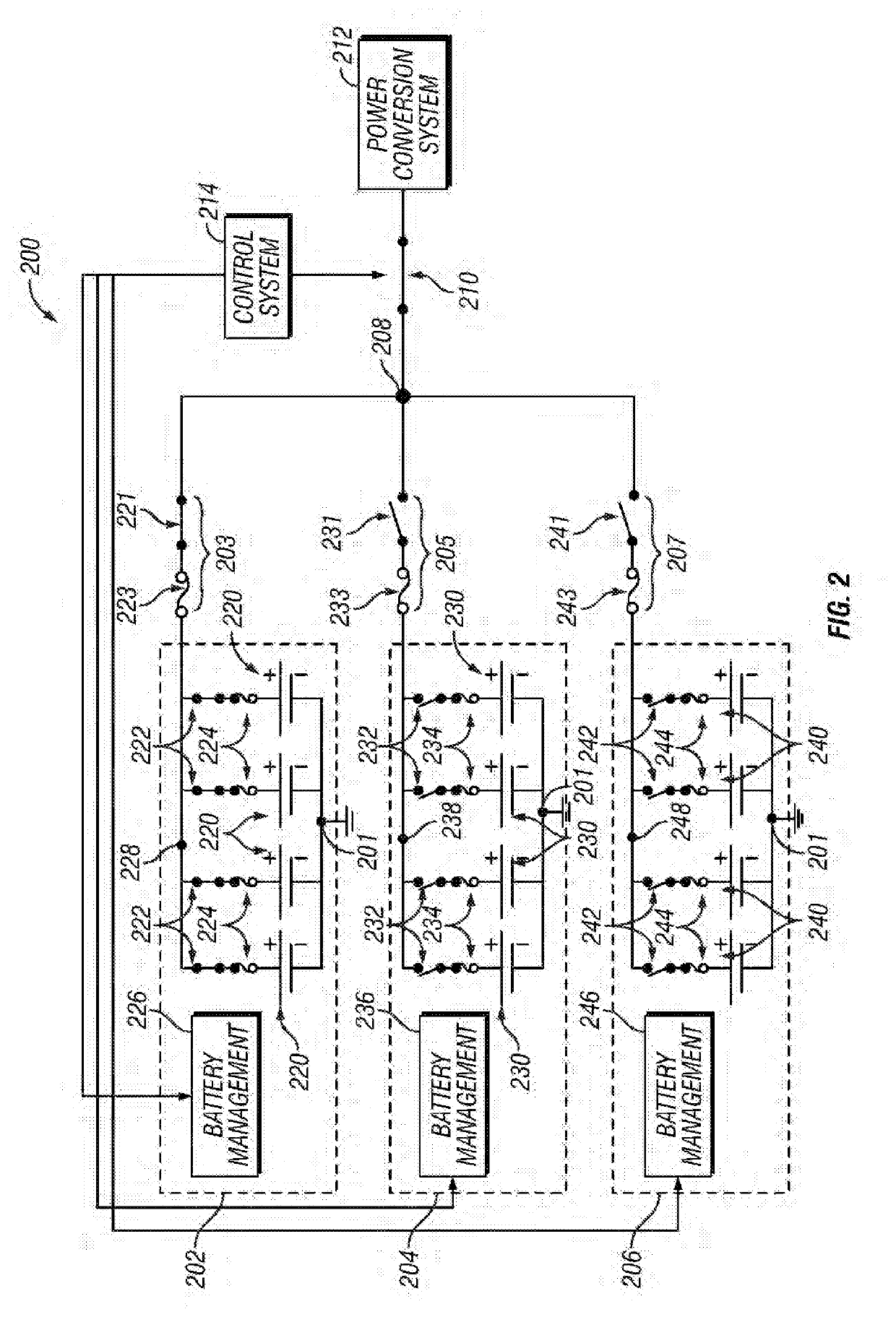
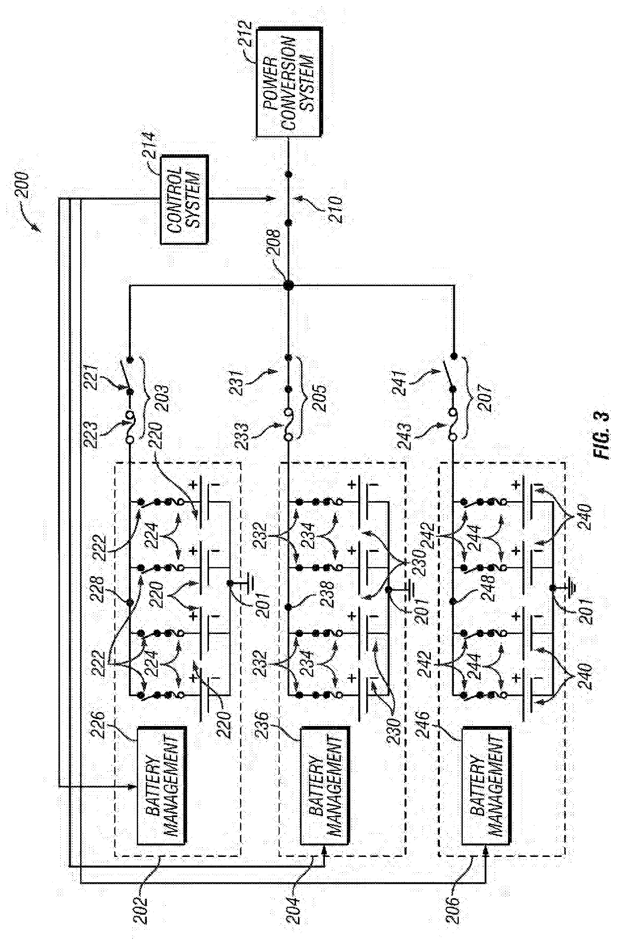
[0011]Embodiments of the subject matter described herein relate to managing short-circuit current levels in an energy storage system that includes multiple energy storage arrangements configured electrically parallel to one another. In exemplary embodiments, individual energy storage arrangements are selectively connected to a power conversion system while other energy storage arrangements of the energy storage system are concurrently disconnected from the power conversion system and one another, thereby limiting the available short-circuit current that an individual energy storage arrangement may be exposed to in the event of a fault. This provides improved fault tolerance by limiting the propagation of potentially damaging fault currents within the energy storage system while also managing or reducing equipment costs by allowing for the use of components with lower current handling capabilities.

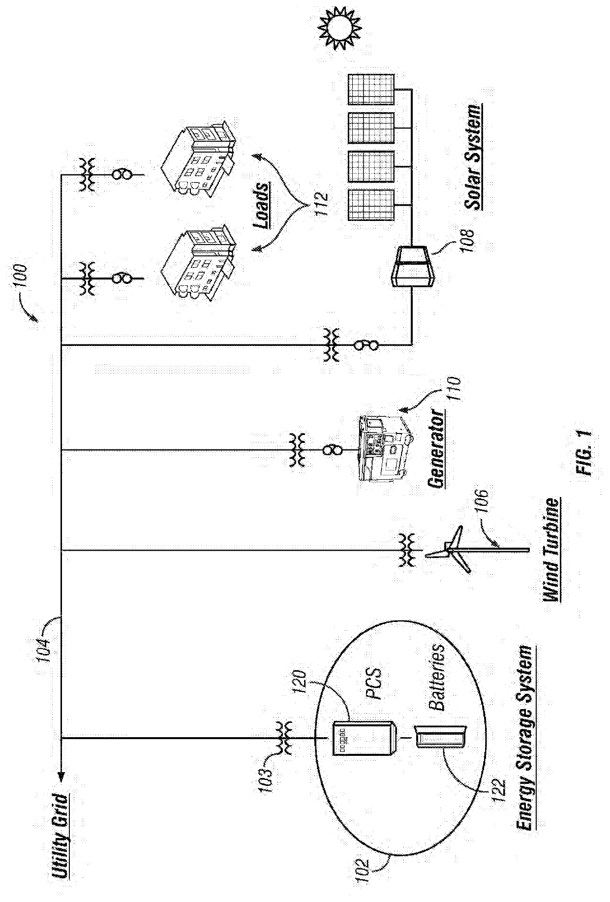
[0012]FIG. 1 depicts an exemplary embodiment of an electrical distribution system 100 t...


PUM


Abstract

Electrical systems and related operating methods are provided. One exemplary electrical system includes a power conversion system, a plurality of battery strings, a plurality of switching arrangements configured electrically in series between the respective battery strings and an interface to the power conversion system, and a control system coupled to the plurality of switching arrangements. The switching arrangements are operated to electrically connect a selected one of the battery strings to the power conversion system while concurrently isolating remaining battery strings from the power conversion system and the selected battery string.

Description

CROSS-REFERENCE TO RELATED APPLICATION[0001]This application claims the benefit of priority from the U.S. Provisional Application No. 62 / 756,281, filed on Nov. 6, 2018, the disclosure of which is hereby expressly incorporated herein by reference for all purposes.TECHNICAL FIELD[0002]The subject matter described herein relates generally to electrical systems, and more particularly, to managing energy storage systems connected to an electrical grid.BACKGROUND[0003]Advances in technology have led to substantial changes to electrical distribution systems as they evolve towards a so-called “smart grid” that supports distributed energy generation from solar, wind, and other distributed energy sources in a resilient and adaptive manner. To this end, energy storage systems are increasingly deployed to capture excess energy that may be subsequently discharged as desired. Lithium ion batteries are commonly utilized due to their availability and relatively low costs; however, their relatively ...

Claims


Application Information

Patent Timeline
Patent Type & Authority Applications(United States)
IPC IPC(8): H02J7/02H02J3/32B60L53/12H02J50/12H02J50/70H02J9/06
CPCH02J9/061H02J3/32H02J7/025H02J50/12H02J50/70B60L53/12H02J7/02H02J7/0048H02J7/00034Y02T10/70Y02T10/7072Y02T90/14
Inventor FACCHINI, KLEBER V.C.BUCKNER, WILLIAM WAYNEWILLIAMS, STEPHEN EBERTSTOCKS, BENJAMIN MAYER
Owner S&C ELECTRIC
Why Eureka
Try Eureka