Catheter atherector

a technology of catheter atherector and catheter atheroscopy, which is applied in the field of improved catheter athereroscopy, can solve the problems of scar formation, blockage of the flow of the vessel, and low blood flow, and achieve the effects of improving the flow rate of the vessel

Active Publication Date: 2020-05-14
MOST CARDIO LLC
View PDF0 Cites 0 Cited by
  • Summary
  • Abstract
  • Description
  • Claims
  • Application Information

AI Technical Summary

Benefits of technology

[0011]The subject invention also discloses a device configured to remove occlusive material from a vessel, comprising: a catheter with a hollow elongated lumen, a proximal opening, and a distal opening, an emulsification reduction sphere within the distal opening of the catheter, wherein the emulsification reduction sphere comprises a substantially spherical shape composed of a plurality of alternating, adjacent protrusions and slots, wherein each protrusion comprises a substantially smooth, curved surface extending outward, and a distal sharp edges and tip, and each slot comprises a substantially smooth, curved surface extending inward; an opening on the emulsification reduction sphere into the distal opening of the catheter within the plurality of protrusions and slots; an emulsification-extraction wire contained within the lumen of catheter, wherein the emulsification-extraction wire comprises a substantially cylindrical screw helical ridge body and forms an internal auger within internal walls of the catheter lumen; a plurality of occlusive material cutters on the distal end of the emulsification-extraction wire extending outwardly from the distal opening of the catheter, wherein the plurality of occlusive material cutters are contained within the plurality of protrusions on the emulsification sphere; wherein the emulsification reduction sphere and the emulsification-extraction wire are configured to each independently rotate in opposite directions and together move axially inside the vessel to engage the occlusive material; wherein the plurality of protrustions shave and scoop the occlusive material into the plurality of occlusive material cutters for emulsification and the plurality of protrusions are configured such that the movement of the plurality of protrusions does not pierce or cut the vessel wall; wherein the distal sharp tips of each protrusion cut the occlusive material into the plurality of occlusive material cutters for emulsification and distal sharp tips are configured to not contact the vessel wall; wherein the mixture of emulsified occlusive material and blood only flows in a proximal direction into the catheter lumen through the plurality of occlusive material cutters, wherein the mixture of emulsified occlusive material and blood is filtered and flows back into the vessel; and wherein during operation of the device, the device is configured such that it does not substantially disrupt blood flow and pressure within the blood vessel.
[0015]The subject invention also discloses a device configured to remove occlusive material from a vessel, comprising: a catheter with a hollow elongated lumen, a proximal opening, and a distal opening, an emulsification reduction sphere surrounding the distal opening of the catheter, wherein the emulsification reduction sphere comprises a substantially spherical shape composed of a plurality of alternating, adjacent protrusions and slots, wherein each protrusion comprises a substantially smooth, curved surface extending outward, and a distal sharp tip, and each slot comprises a substantially smooth, curved surface extending inward; an opening on the emulsification reduction sphere into the distal opening of the catheter within the plurality of protrusions and slots; an emulsification-extraction wire contained within the lumen of catheter, wherein the emulsification-extraction wire comprises a substantially cylindrical screw helical ridge body and forms an internal auger within internal walls of the catheter lumen; a plurality of occlusive material cutters on the distal end of the emulsification-extraction wire extending outwardly from the distal opening of the catheter, wherein the plurality of occlusive material cutters are contained within the plurality of protrusions on the emulsification sphere; wherein the emulsification reduction sphere and the emulsification-extraction wire are configured to each independently rotate and move axially inside the vessel to engage the occlusive material; wherein the plurality of protrustions shave and scoop the occlusive material into the plurality of occlusive material cutters for emulsification and the plurality of protrusions are configured such that the movement of the plurality of protrusions does not pierce or cut the vessel wall; wherein the distal sharp tips of each protrusion cut the occlusive material into the plurality of occlusive material cutters for emulsification and distal sharp tips are configured to not contact the vessel wall; wherein the mixture of emulsified occlusive material and blood only flows in a proximal direction into the catheter lumen through the plurality of occlusive material cutters, wherein the mixture of emulsified occlusive material and blood is filtered and flows back into the vessel; and wherein during operation of the device, the device is configured such that it does not substantially disrupt blood pressure within the blood vessel.
[0017]The subject invention also discloses an atherectomy catheter configured to remove plaque from a vessel, comprising: a catheter with a hollow elongated lumen, a proximal opening, and a distal opening, an emulsification reduction sphere surrounding the distal opening of the catheter, wherein the emulsification reduction sphere comprises a substantially spherical shape composed of a plurality of alternating, adjacent protrusions and slots, wherein each protrusion comprises a substantially smooth, curved surface extending outward, and a distal sharp tip, and each slot comprises a substantially smooth, curved surface extending inward; an opening on the emulsification reduction sphere into the distal opening of the catheter within the plurality of protrusions and slots; an emulsification-extraction wire contained within the lumen of catheter, wherein the emulsification-extraction wire comprises a substantially cylindrical screw helical ridge body and forms an internal auger within internal walls of the catheter lumen, a plurality of plaque cutters on the distal end of the emulsification-extraction wire extending outwardly from the distal opening of the catheter, wherein the plurality of plaque cutters are contained within the plurality of protrusions on the emulsification sphere; wherein the emulsification reduction sphere and the emulsification-extraction wire each rotate and move axially inside the vessel to engage the plaque, wherein the plurality of protrustions shave and scoop the plaque into the plurality of plaque cutters for emulsification and the movement of the plurality of protrusions does not pierce or cut the vessel wall; wherein the distal sharp tips of each protrusion cut the plaque into the plurality of plaque cutters for emulsification and distal sharp tips do not contact the vessel wall; wherein the mixture of emulsified plaque and blood only flows in a proximal direction into the catheter lumen through the plurality of plaque cutters, wherein the mixture of emulsified plaque and blood is filtered and flows back into the vessel; and wherein during operation of the device does not substantially disrupt blood pressure within the blood vessel.
[0020]The subject invention further discloses a device configured to remove occlusive material from a vessel, comprising: a catheter with a hollow elongated lumen, a proximal opening, and a distal opening, an emulsification reduction sphere surrounding the distal opening of the catheter, wherein the emulsification reduction sphere comprises a plurality of alternating, adjacent protrusions and slots, wherein each protrusion comprises a substantially smooth, curved surface and a distal sharp tip, and each slot comprises a substantially smooth, curved surface; an opening on the emulsification reduction sphere into the distal opening of the catheter within the plurality of protrusions and slots; an emulsification-extraction wire contained within the lumen of catheter, wherein the emulsification-extraction wire comprises a substantially cylindrical screw helical ridge body; an occlusive material cutter on the distal end of the emulsification-extraction wire extending outwardly from the distal opening of the catheter, wherein the occlusive material cutter is contained within the plurality of protrusions on the emulsification sphere; wherein the emulsification reduction sphere and the emulsification-extraction wire each rotate and move axially inside the vessel to engage the occlusive material, wherein the plurality of protrustions shave and scoop the occlusive material into the occlusive material cutter for emulsification and the movement of the plurality of protrusions does not pierce or cut the vessel wall; wherein the distal sharp tips of each protrusion cut the occlusive material into the occlusive material cutter for emulsification and distal sharp tips do not contact the vessel wall; and wherein the mixture of emulsified occlusive material and blood only flows in a proximal direction into the catheter lumen through the plurality of occlusive material cutters, wherein the mixture of emulsified occlusive material and blood is filtered and flows back into the vessel; and wherein operation of the device does not substantially disrupt blood pressure within the blood vessel.

Problems solved by technology

Over time these plaques can become large enough to reduce or occlude blood flow through the vessels, leading to symptoms of low blood flow.
However, atherectomy catheters and devices often undesirably cut, perforate, tear and stretch the vessel, causing scar formation.
Such scar tissue causes inflammation, stenosis and blocks flow in the vessel and often needs to be removed.
Furthermore, atherectomy catheters often run at high speeds causing temperature and causing damage to the vessels.
Finally, atherectomy catheters block arterial blood flow completely during plaque removal, resulting in high vessel blood pressure, and posing a danger to the patient.

Method used


Image

  • Catheter atherector
  • Catheter atherector
  • Catheter atherector

Examples


Embodiment Construction

[0051]While several variations of the present invention have been illustrated by way of example in particular embodiments, it is apparent that further embodiments could be developed within the spirit and scope of the present invention. However, it is to be expressly understood that such modifications and adaptations are within the spirit and scope of the present invention, and are inclusive, but not limited to the following appended claims as set forth.

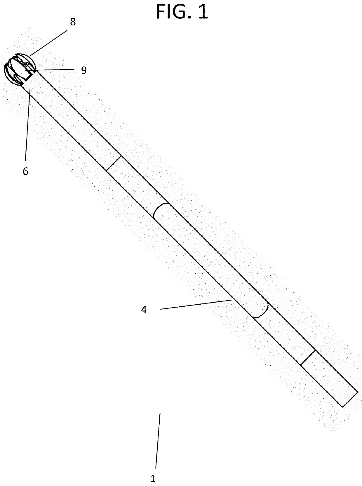
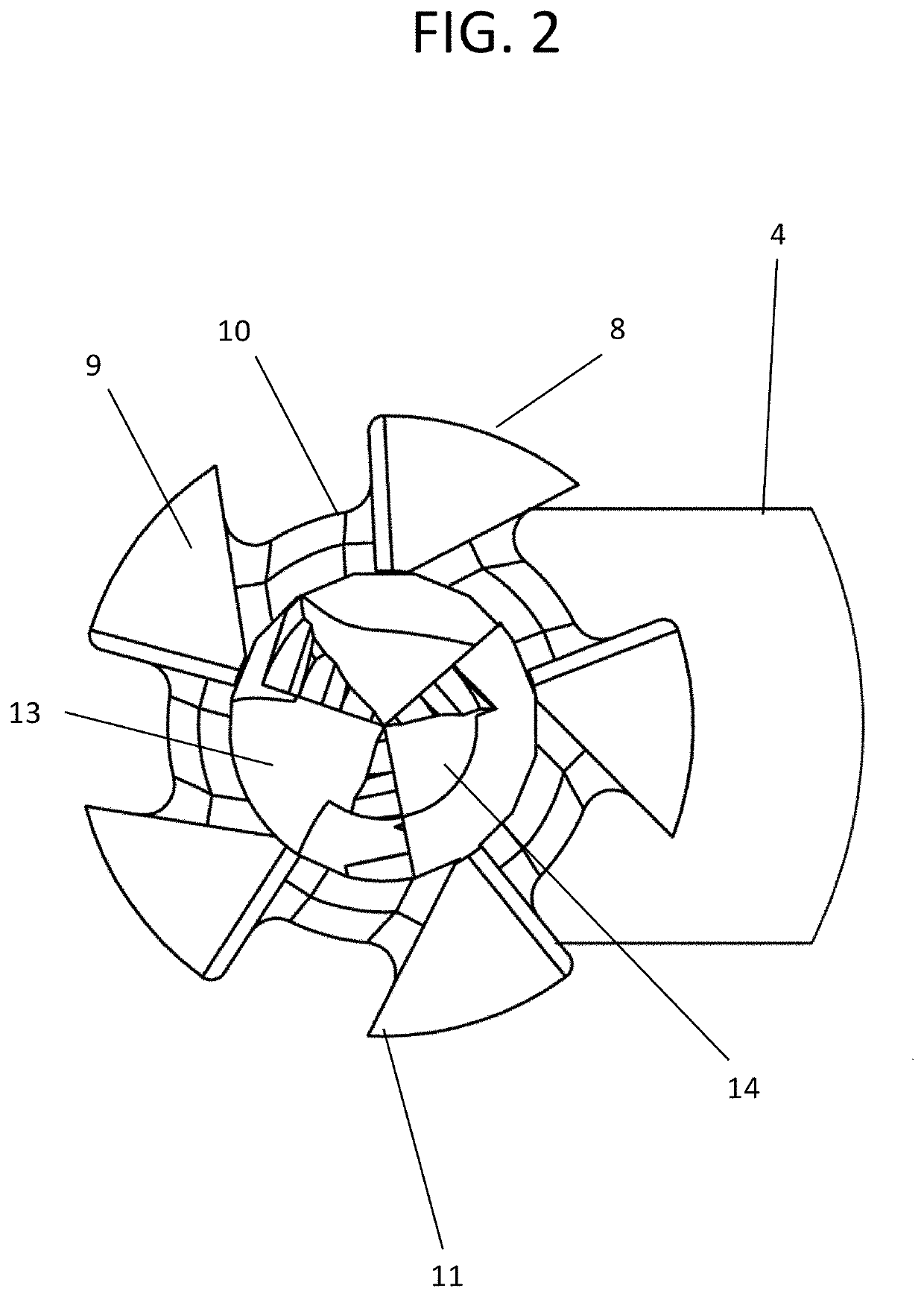
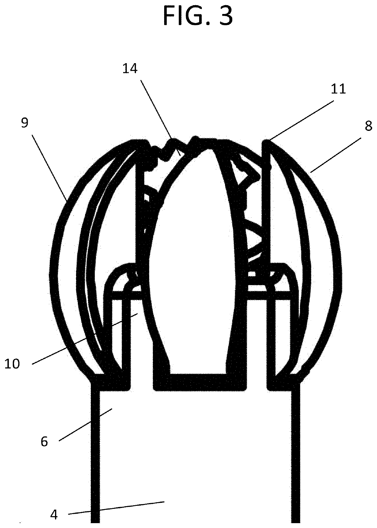
[0052]As illustrated in FIGS. 1-15, the subject invention discloses a catheter atherector for use in minimally invasive intravascular plaque removal from inner walls 2 of blood vessels 3.

[0053]The catheter atherector 1 comprises a catheter 4 containing a hollow elongated lumen 5 with a distal end 6 with an opening 7 surrounded by a slotted emulsification reduction sphere 8. In embodiments of the subject invention, the catheter 4 has a diameter of 1 to 6 millimeters. The slotted emulsification reduction sphere 8 contains a plurality of...


PUM


Abstract

An improved catheter atherector for shaving, cutting, and emulsifying accumulated plaque into fine particles, and removing the particles from blood vessel walls without cutting or permanently stretching the walls, and without substantially blocking the blood flow through the vessel during plaque removal operation. The catheter atherector includes an emulsification reduction sphere and extraction wire that rotate and move axially inside the vessel to engage the occlusive material. Emulsified occlusive reduced plaque material and blood only flow in a proximal direction into a catheter lumen. The operation of the device does not substantially disrupt blood pressure within the blood vessel.

Description

CROSS REFERENCE TO RELATED APPLICATION[0001]This application claims the benefit of U.S. Provisional Patent Application No. 62 / 767,283 filed on Nov. 14, 2018, the contents of which are incorporated herein by reference.FIELD OF THE INVENTION[0002]This invention relates to an improved catheter atherector for shaving, cutting, and emulsifying accumulated plaque from blood vessel walls into small particles, without cutting or permanently stretching the walls, and without substantially blocking the blood flow through the vessel during plaque removal operation, with removing the plaque from cardiovascular system without allowing it to flow downstream.BACKGROUND OF INVENTION[0003]Atherosclerosis is a form of arteriosclerosis in which plaque accumulates in an arterial vessel and the artery wall thickens as a result of invasion and accumulation of white blood cells on the inner artery vessel walls. These plaque accumulations contain both living, active WBCs (producing inflammation) and remnan...

Claims


Application Information

Patent Timeline
Patent Type & Authority Applications(United States)
IPC IPC(8): A61B17/3207
CPCA61B2017/320775A61B17/320783A61B17/320725A61B17/320758A61B2017/00685A61B2090/08021
Inventor MENN, PAVEL
Owner MOST CARDIO LLC
Why Eureka
Try Eureka