Pressure compensating molding system

a molding system and pressure compensation technology, applied in the field of molding systems, can solve the problems of difficulty in controlling the mold temperature, large mold volume and structural strength, and high thermal mass of molds, and achieve the effect of reducing the heat loss of molding materials

Inactive Publication Date: 2011-10-11
DELTA PT
View PDF61 Cites 0 Cited by
  • Summary
  • Abstract
  • Description
  • Claims
  • Application Information

AI Technical Summary

Benefits of technology

[0011]Minimizing the thermal mass of the mold aids in reducing the injection pressure by reducing the thermal lag for heating and / or cooling a mold to accommodate the temperature requirements for the molding material, thereby producing high quality molded objects quickly and repeatably. The present invention minimizes the thermal mass by separating the molding cavity from a heating / cooling fluid cavity with a thin member having good heat transfer properties. In one such embodiment, the fluid cavity is insulated from a platen. Deformation of the thin member by the pressure of the molding material entering the mold cavity is prevented / controlled by pressurizing the fluid in the fluid cavity to match the pressure of the molding material in the mold cavity.
[0012]In various embodiments, obstructions positioned inside the fluid cavity disrupt the flow of the fluid in the fluid cavity, thereby causing turbulent flow conditions and ensuring uniform fluid, and thermal, distribution in the fluid cavity. Stanchions positioned in the fluid cavity and extending to the thin member serve to maintain stability of the mold cavity by preventing deformation of the thin member defining the mold cavity. In one such embodiment, the stanchions have a through-opening that allows passage of an ejector or a slide into the mold cavity. The hollow stanchions form a seal between the mold cavity and the fluid cavity around the opening for the ejector or slide.
[0013]In one embodiment, an insulator is positioned on the fluid cavity side of the sheet adjacent the portion of the mold cavity desired to limit the heat transfer rate to locally control the heat transfer rate of a portion of the mold cavity surface to produce a desired effect on the molded object.
[0014]According to one embodiment of the present invention, a pressure compensating molding system is provided. The molding system includes a mold with two halves or sections. Each mold half includes a die sheet that separates the mold cavity from a heating / cooling cavity. The die sheet has a surface shaped to produce a desired component. The shape of the die sheet is maintained during molding by monitoring the pressure in the mold cavity and in the heating / cooling cavity behind the die sheet, and controlling the pressure in the heating / cooling cavity to be substantially equal to the pressure in the molding cavity. The die sheet is a relatively thin sheet that provides for rapid heating and cooling. The heating / cooling cavity receives fluid of an appropriate temperature to control the temperature of the die sheet. By injecting heated fluid into the heating / cooling cavity, the die sheet temperature is raised to a desired temperature prior to and / or during the molding stage thereby increasing moldability and improving the quality of the molded components. In various embodiments, the desired temperature ranges from an ambient room temperature up to above the softening or melting temperature of the molding material. In one embodiment, the heated fluid is steam. In another embodiment, the heated fluid is a liquid.
[0017]In another embodiment, the molding system includes a melt pipe. The melt pipe is a jacketed conduit. The conduit is defined by a thin member that separates the conduit from the jacket. The jacket receives fluid at a specified temperature and pressure to minimize the heat loss of the molding material in the conduit. The melt pipe allows transporting of the molding material to another section of the mold cavity while maintaining the molding material temperature within limits. The melt pipe also allows the molding material to be transported to a second, or cascaded, mold. In various embodiments, the melt pipe is configured to allow removal of solidified molding material either by being longitudinally hinged or by having an ejector push the solidified melt out of the conduit.

Problems solved by technology

The high injection pressure requires that the mold be massive and have sufficient structural strength to prevent the mold cavity from deforming when subjected to high injection pressures.
Because molds are massive to withstand the high injection pressures, the molds have high thermal mass.
But, the high thermal mass results in difficulties in controlling the mold temperature.

Method used


Image

  • Pressure compensating molding system
  • Pressure compensating molding system
  • Pressure compensating molding system

Examples


Embodiment Construction

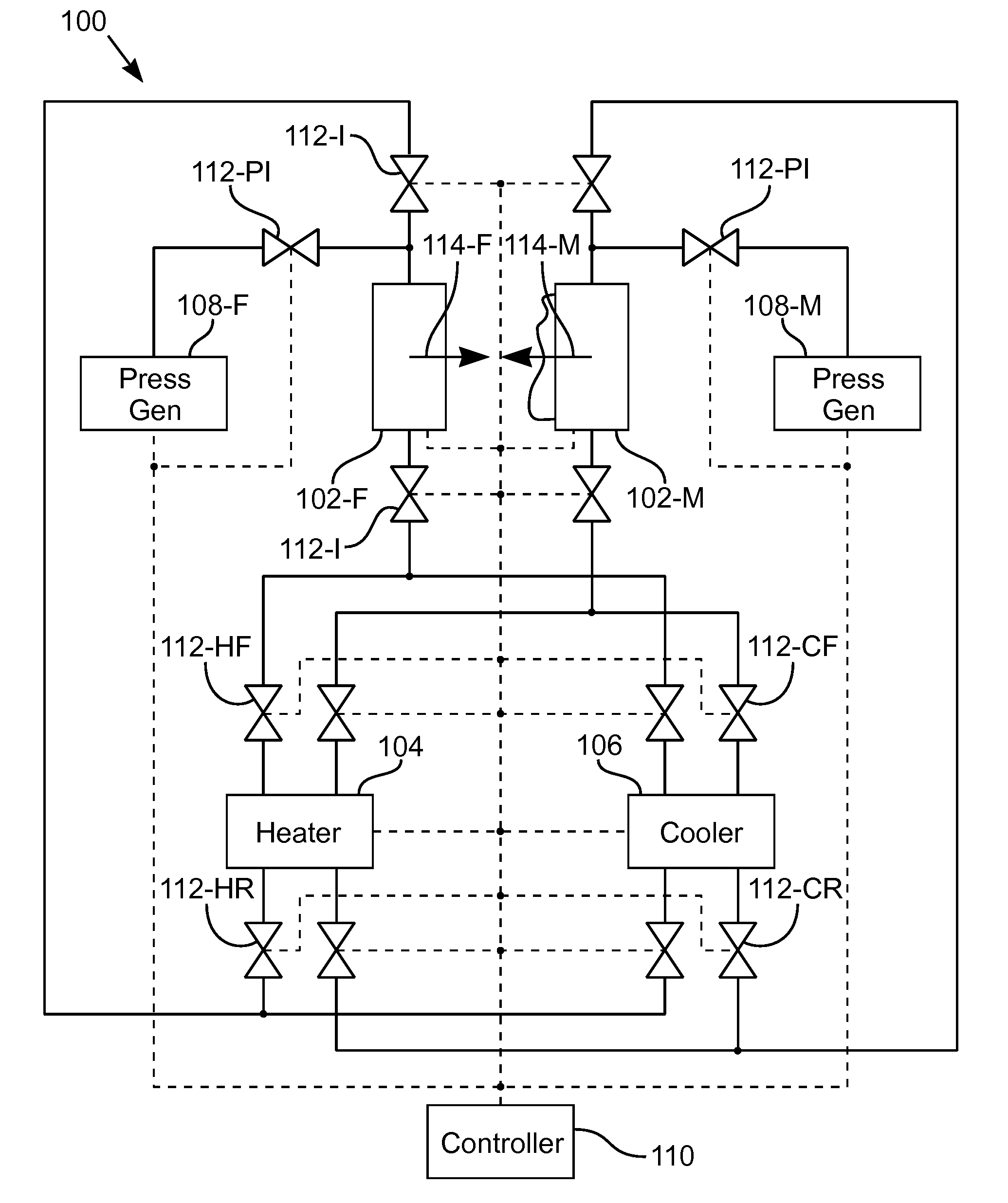
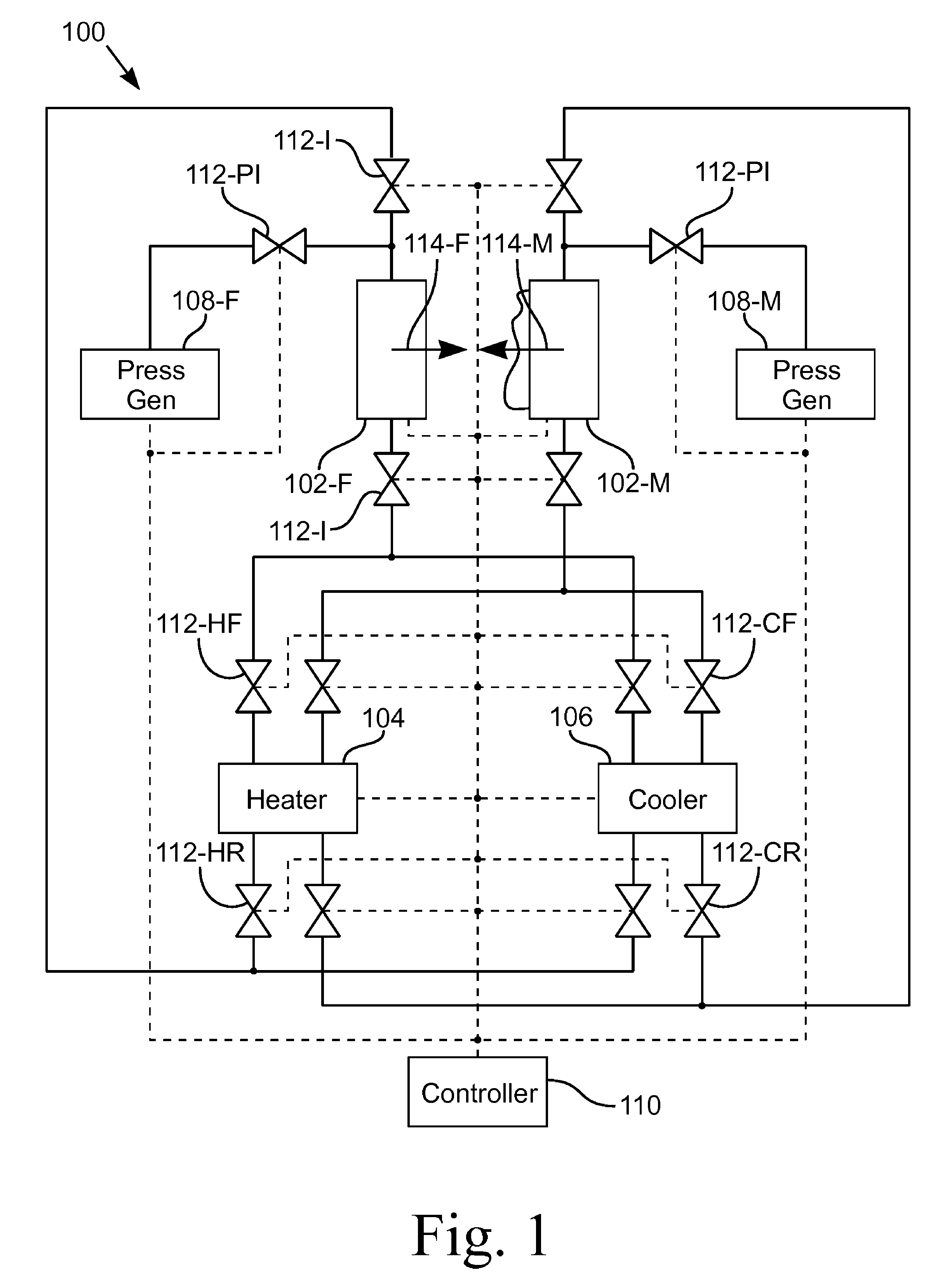
[0030]An apparatus for and a method of operating a pressure compensating molding system 100 are disclosed. It is desirable to maintain the mold die surfaces 402 at a high temperature during the beginning of the molding cycle in order to maintain the molding material 218 in a molten or semi-molten state as it fills the mold cavity 204. With a higher and more consistent temperature across the mold die surfaces 402, less pressure is required for forcing the molding material 218 into the mold and less imperfections on the molded component surface will result. Although the following description uses injection molding as an example, the molding system 100 is suitable for other plastic molding processes, such as structural foam molding low pressure molding, transfer molding, and blow molding. The system 100 is also suitable for processing thixotropic plastic and metal alloys.

[0031]FIG. 1 illustrates a piping and control diagram of one embodiment of the pressure compensating molding system ...


PUM

PropertyMeasurementUnit
mold pressureaaaaaaaaaa
cavity pressureaaaaaaaaaa
pressureaaaaaaaaaa

Abstract

A pressure compensating molding system with die faces of thin sheets. A thin die sheet separates a mold cavity from a heating / cooling cavity. A heating system causes a heated fluid to flow through the heating / cooling cavity, thereby preheating the thin sheet. The injection material is forced through a sprue into the mold cavity. Pressure sensors monitor the pressure of the injection material in the mold cavity and in the heating / cooling cavity. A controller varies the pressure in the heating / cooling cavity to equalize a pressure differential across the thin die sheet. A cooling system causes a cooling fluid to flow through the heating / cooling cavity to cool the molded component.

Description

CROSS-REFERENCE TO RELATED APPLICATIONS[0001]This application claims the benefit of U.S. Provisional Application No. 60 / 957,834, filed Aug. 24, 2007.STATEMENT REGARDING FEDERALLY SPONSORED RESEARCH OR DEVELOPMENT[0002]Not ApplicableBACKGROUND OF THE INVENTION[0003]1. Field of Invention[0004]This invention pertains to a molding system. More particularly, this invention pertains to a molding system in which the die faces are formed of thin sheets that are heated and cooled on demand by a fluid outside the mold cavity. Further, the dimensional stability of the thin sheets is maintained by equalizing the pressure between the mold cavity and the fluid cavities on the opposite side of each thin sheet.[0005]2. Description of the Related Art[0006]A common manufacturing method is molding in which a material is placed in a cavity and the material is set or cured to conform to the shape of the cavity. For example, one type of molding process is injection molding, which involves injecting a mol...

Claims


Application Information

Patent Timeline
Patent Type & Authority Patents(United States)
IPC IPC(8): B29C45/76
CPCB29C43/58B29C2043/5808
Inventor SEVIGNY, ROBERT
Owner DELTA PT
Why Eureka
Try Eureka