Knee flexion and extension gap tensioning and measuring method

a gap tensioning and measuring method technology, applied in osteosynthesis devices, prosthesis, applications, etc., can solve the problems of inability to balance with the patella in-place, difficulty and complexity in achieving proper balance, and overly complicated devices

Active Publication Date: 2020-05-21
LITTLE ENGINE LLC
View PDF10 Cites 18 Cited by
  • Summary
  • Abstract
  • Description
  • Claims
  • Application Information

AI Technical Summary

Benefits of technology

[0009]According to another aspect of the invention, a method for balancing extension and flexion gaps between the tibia and the femur of a knee joint, including: making a tibial cut along the first cutting plane to cut away a distal portion of the tibia, and making a distal femoral cut along a second cutting plane to cut away a distal portion of the femur, such that an extension gap is defined between the first and second cutting planes; positioning the knee joint in extension and inserting a gap tensioner into the extension gap, the gap tensioner including: a baseplate; a top plate; a linkage interconnecting the baseplate and the top plate and operable to move the gap tensioner between retracted and extended positions; and wherein the top plate is pivotally connected to the linkage so as to be able to freely pivot about a pivot axis; actuating the linkage to move the gap tensioner towards the extended p

Problems solved by technology

One problem with prior art balancing techniques is that it is difficult and complex to achieve the proper balance.
Current state-of-the-art gap balancin

Method used


Image

  • Knee flexion and extension gap tensioning and measuring method
  • Knee flexion and extension gap tensioning and measuring method
  • Knee flexion and extension gap tensioning and measuring method

Examples


Embodiment Construction

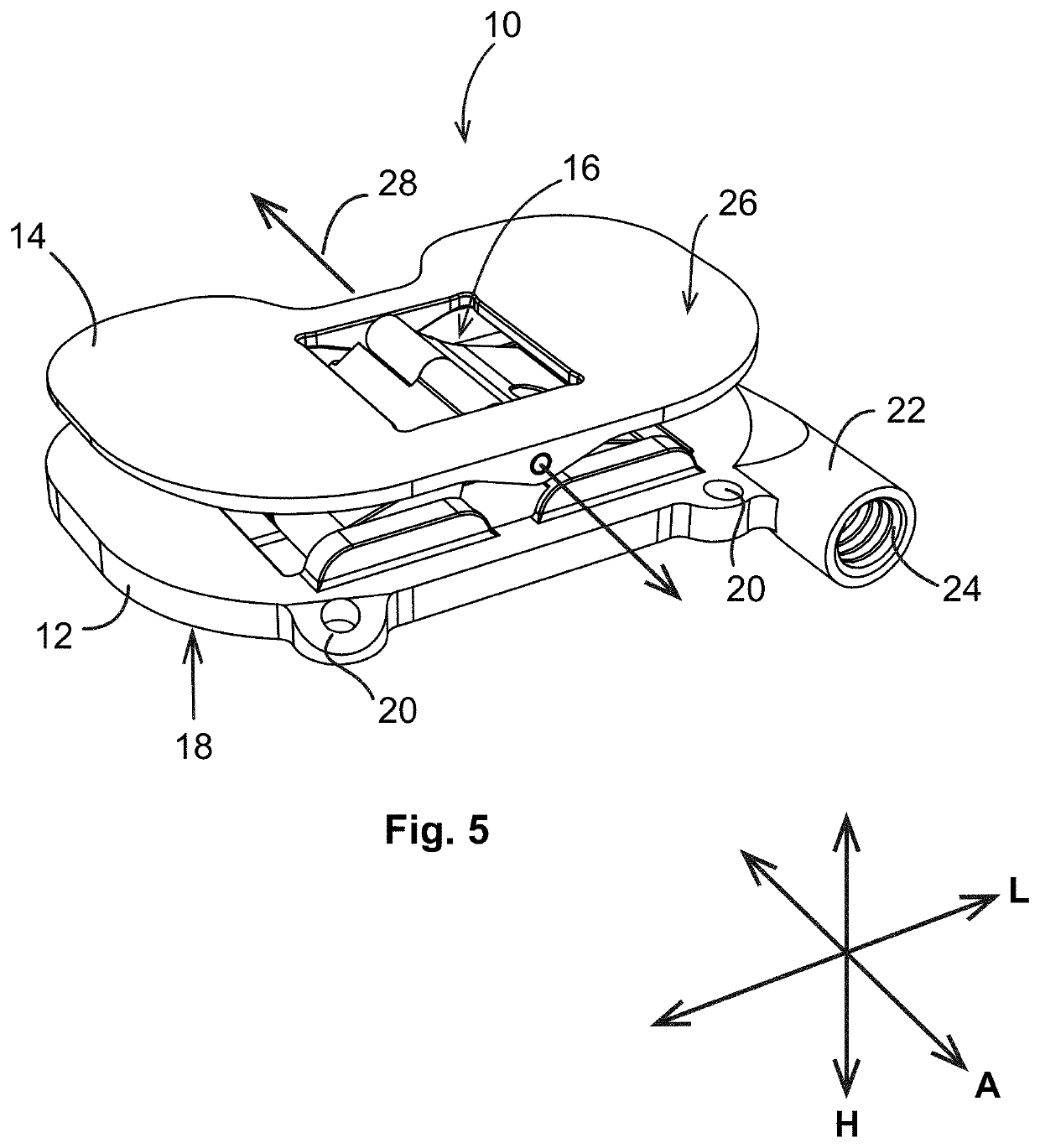
[0095]Referring to the drawings wherein identical reference numerals denote the same elements throughout the various views, FIG. 5 depicts an exemplary gap tensioner 10 (alternatively referred to as a “jack”) which is useful for balancing a gap a human knee joint as part of a total knee arthroscopy. In one aspect, the gap tensioner 10 may be described as having the ability to constrain or fix four degrees of freedom of a knee joint while permitting controlled movement of two degrees of freedom.

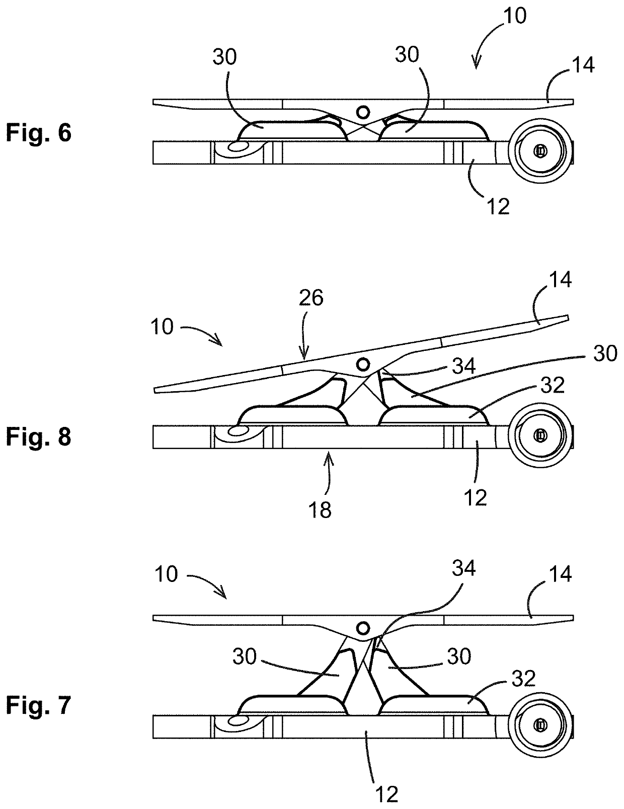
[0096]The gap tensioner 10 comprises a baseplate 12 and a top plate 14 interconnected by a linkage 16. The linkage 16 and the gap tensioner 10 are movable between a retracted position in which the top plate 14 lies close to or against the baseplate 12, and an extended position in which the top plate 14 is spaced away from the baseplate 12. As described in more detail below, a mechanism is provided to actuate the linkage 16 in response to an actuating force in order to separate the baseplate 12...


PUM


Abstract

A method for imparting tension across a human knee joint which includes a femur bone, a tibia bone, a patella bone, a patellar tendon, and ligaments, wherein the ligaments and patellar tendon are under anatomical tension to connect the femur and tibia together, creating a load-bearing articulating joint. The method includes: providing a tensioning device, including: a baseplate; a top plate; and a linkage interconnecting the baseplate and the top plate and operable to move the tensioning device between retracted and extended positions, wherein the top plate is pivotally connected to the linkage so as to be able to freely pivot about a pivot axis; positioning the tensioning device between the femur and the tibia; applying an actuating force to the linkage to move the tensioning device towards the extended position, so as to impart a controlled separating force driving the femur and tibia apart to extend the ligaments.

Description

[0001]This invention relates generally to medical devices and instruments, and more particularly to a method for applying tension along or across a human knee joint to take measurements to repair, augment, or replace it.BACKGROUND[0002]Total knee arthroplasty (“TKA”) is a procedure for treating an injured, diseased, or worn human knee joint. In a TKA, an endoprosthetic joint is implanted, replacing the bearing surfaces of the joint with artificial members. Proper alignment of the joint and substantially equal tension in the soft tissues surrounding the joint are important factors in producing a good surgical outcome.[0003]A human knee joint “J” is shown in FIG. 1-4. The joint J is prepared for implantation by cutting away portions of the femur “F” and the tibia “T”. FIGS. 1 and 2 show the joint in extension, with cutting planes for a tibial cut 1 and a distal femoral cut 2. The tibial cut 1 and the distal formal cut 2 cooperate to define an extension gap “EG”. FIGS. 3 and 4 show the...

Claims


Application Information

Patent Timeline
IPC IPC(8): A61B17/02A61B17/88A61B17/17
CPCA61B17/154A61B17/025A61B2017/681A61B2017/564A61B2017/565A61B2017/0268A61B17/8869A61B17/1675A61B2090/067A61B17/1764A61B2017/00845A61B17/1604A61B17/155A61B5/4585A61B5/4528A61B2090/061A61F2/4684A61B5/1121A61B2090/064A61B34/20A61B2017/567
Inventor COLE, J. DEANKELLAR, FRANZ W.BISSETTE, MICHAEL D.KELLAR, FRANZ AUSTEN
Owner LITTLE ENGINE LLC
Why Eureka
Try Eureka