Massage apparatus, systems and methods

Active Publication Date: 2020-05-21
RLSMITH HLDG LLC
View PDF0 Cites 1 Cited by
  • Summary
  • Abstract
  • Description
  • Claims
  • Application Information

AI Technical Summary

Benefits of technology

[0004]One aspect of the present application is the recognition that traditional massage systems and devices do not sufficiently facilitate movement of a percussive massage tool over a treatment area of a patient while providing specialized treatment. Certain embodiments described herein can include a massage tool having a platform. The platform can include a surface positioned to contact a treatment area during a massage treatment procedure. The platform can provide stability and repeatability during a treatment procedure while the massage tool is moved about the treatment region.
[0005]The platform can also define an opening through which a massage head can extend and retract to contact a treatment region of a patient during a treatment procedure. The opening can be positioned laterally within an interior section of the platform such that the platform can laterally extend around the opening on all sides. By surrounding the opening through which the massage head extends, the platform can at least partially control the interaction of the massage head with a treatment region of the patient. A height of the platform can at least partially define a depth of tissue penetration of the massage head at a treatment region of a patient. A width of the platform can affect positioning of the tool within certain body areas. A length of the platform can affect the maneuverability and stability of the massage tool over the treatment region of a patient. In certain embodiments, the platform can have heights, widths, and lengths that vary at different portions of the platform. In certain embodiments, the platform can have a profile shaped to fit a particular shape or use. A length of the platform in front of the opening in the platform can add stability and at least partially control an angle of treatment by the massage tool by preventing or restricting forward tipping or rotation of the massage tool. A length of the platform behind the opening in the platform can add stability and at least partially control an angle of treatment by the massage tool by preventing or restricting backward tipping or rotation of the massage tool. The foregoing features of the massage tool can provide for repeatability and consistency of a massage treatment over a treatment area. By controlling features such as depth of penetration, angle of treatment, and stability, the platform can also provide for a safer massage treatment. By surrounding the massage head, the platform can also protect the massage head and/or a connector between the massage head and a body of the massage tool from deflection or limit exposure to forces that can cause deflection from contacting the massage head and/or connector.
[0006]In addition to the advantages described above, certain embodiments described herein can include a cover that can at least partially surround the connector and/or massage head. In combination with the platform and platform opening, the cover can at least partially control and enclose an actuation channel in which reciprocal motion of the connector and massage head occurs. The channel can be generally enclosed and can be surrounded by portions of the massage tool, such as the cover, the platform, the body, or any other portion. The massage head and connector can freely reciprocate in the actuation channel. By enclosing the actuation channel, the massage tool can prevent potential damage to enclosed portions of the massage head and connector. Enclosing the actuation channel can also prevent injury caused by contact of the connector with a user or patient.
[0007]Another aspect of present application is the recognition that the massage heads of traditional massage trea

Problems solved by technology

A massage head that is formed from a material that is too soft may disconnect from a mas

Method used


Image

  • Massage apparatus, systems and methods
  • Massage apparatus, systems and methods
  • Massage apparatus, systems and methods

Examples


Example

[0072]The following detailed description is directed to certain specific embodiments. The invention(s) disclosed herein, however, can be embodied in a multitude of different ways as defined and covered by the claims. In this description, reference is made to the drawings, wherein like parts are designated with like numerals throughout. The features, aspects and advantages of the present invention will now be described with reference to the drawings of several embodiments that are intended to be within the scope of the development herein disclosed. These and other embodiments will become readily apparent to those skilled in the art from the following detailed description of the embodiments having reference to the attached figures, the invention not being limited to any particular embodiment(s) herein disclosed.

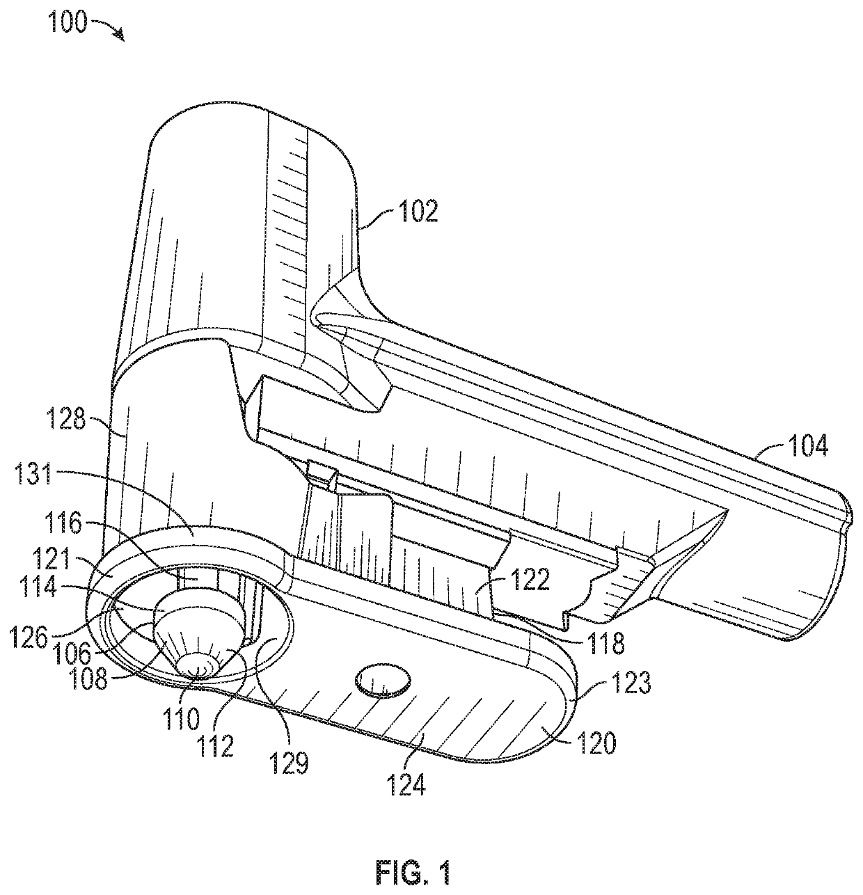
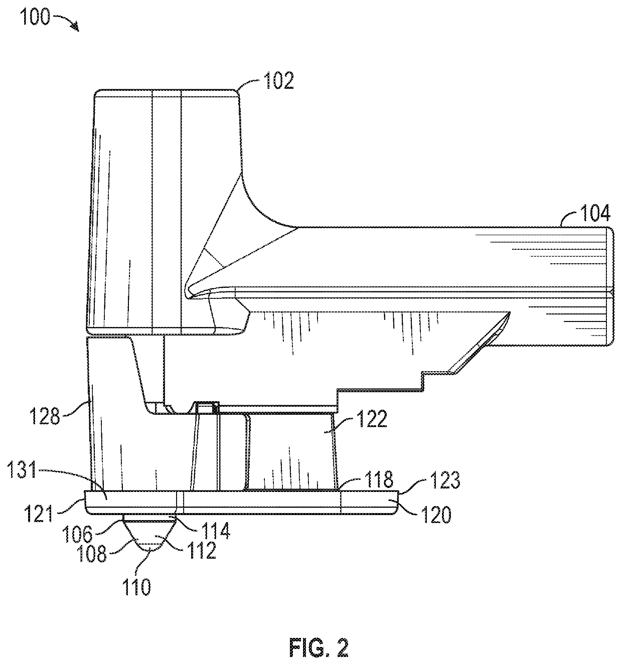
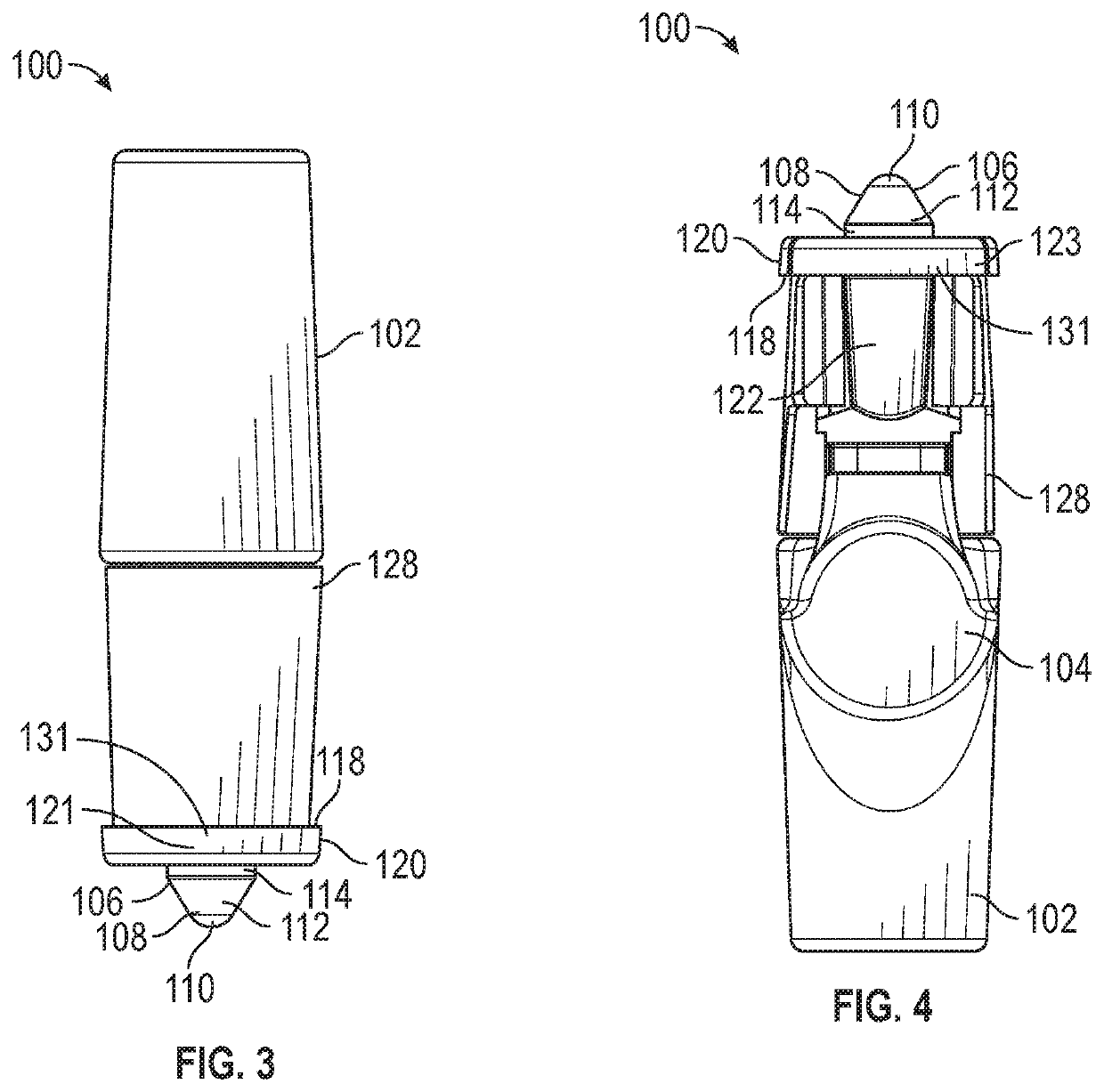
[0073]According to some preferred embodiments, the devices, systems, and methods described herein relate to a massage tool. The massage tool can be used to perform percussive m...


PUM


Abstract

A massage system includes a massage head configured to contact a treatment region of a patient during a massage treatment procedure, a body having a handle, a connector having a first end and a second end, wherein the first end is releasable secured to the body and the second end is coupled to the massage head, a motor positioned within the body and configured to drive movement of the massage head relative to the body, and a platform configured to be placed against the patient during a massage treatment procedure. The platform defines an opening. The platform is positioned so that the massage head extends at least partially through the opening during movement of the massage head relative to the body, and the platform surrounds the massage head in at least one dimension during movement of the massage head relative to the body.

Description

BACKGROUNDField[0001]The present disclosure relates to massage therapy, and more particularly, relates to systems, methods, and apparatuses for motor-powered massage therapy.Description of the Related Art[0002]Percussive massage techniques provide concentrated, rapid, short-duration pulses deep into the tissue of the body. In some instances, percussive massage can be performed manually by a massage therapist striking a patient with soft blows using rapid movements from the wrists. Alternatively, mechanical electrical devices may be used to provide concentrated, rapid, short-duration pulses to the patient.SUMMARY[0003]Described herein are some embodiments of a massage system. Methods for performing massage therapy are also included. These massage systems and related methods are described in greater detail below.[0004]One aspect of the present application is the recognition that traditional massage systems and devices do not sufficiently facilitate movement of a percussive massage too...

Claims


Application Information

Patent Timeline
IPC IPC(8): A61H23/00A61H7/00A61H23/02A61H15/00
CPCA61H23/0254A61H2201/0153A61H23/006A61H15/0085A61H7/001A61H2023/002A61H1/00A61H2201/0173A61H2201/0192A61H2201/1207A61H2201/1645A61H2201/1664A61H2201/1685A61H2201/1695A61H2201/5023A61H2205/04A61H2205/06A61H2205/081A61H2205/086A61H2205/088A61H2205/106A61H2205/108A61H2205/12
Inventor SMITH, JR., RICHARD LOYZISKA, MITCHELL EDMUNDLEOPOLD, JERRY DOUGLASPALMA, JR., JAMES ALAN
Owner RLSMITH HLDG LLC
Why Eureka
Try Eureka