
Painting Device and Painting Apparatus

a painting device and painting technology, applied in the direction of liquid spraying apparatus, coatings, spray nozzles, etc., can solve the problems of paint being applied to undesired areas, and the use of hand-held paint rollers is often very labor-intensive and time-consuming, and achieves less tiring

Inactive Publication Date: 2020-05-21
CPR GRP AUSTRALIA PTY LTD
View PDF7 Cites 3 Cited by
  • Summary
  • Abstract
  • Description
  • Claims
  • Application Information

AI Technical Summary

Benefits of technology

The invention is a painting device with a shroud that shields the paint sprayed from the nozzle from external influences and confines the paint to a specific area. The shroud includes panels or walls that help apply the paint evenly and consistently to the surface, regardless of weather conditions. The device also has multiple nozzles that can be used simultaneously, increasing the width of the strip of paint applied. Additionally, the invention provides an extension pole and belt or harness for the operator to easily hold and manipulate the device and support the weight of the reformer and rollers, making the operation more comfortable and efficient.

Problems solved by technology

Although hand-held paint rollers can provide a consistent finish, the use of hand-held paint rollers is often very labour intensive and time consuming, especially when painting large surfaces.
Also, paint can often drip from the paint applicator while painting and cause paint to be applied on undesired areas.
However, there is a risk of over spray and splatter that can result in undesired areas being applied with paint.
This risk is exacerbated in outdoor environment in which the spray of paint can be heavily affected by wind.
Further, given that thinned paint is generally used in paint sprayers, there is an increased risk of drips and runs occurring after the paint has been applied to the surface.

Method used


Image

  • Painting Device and Painting Apparatus
  • Painting Device and Painting Apparatus
  • Painting Device and Painting Apparatus

Examples


Embodiment Construction

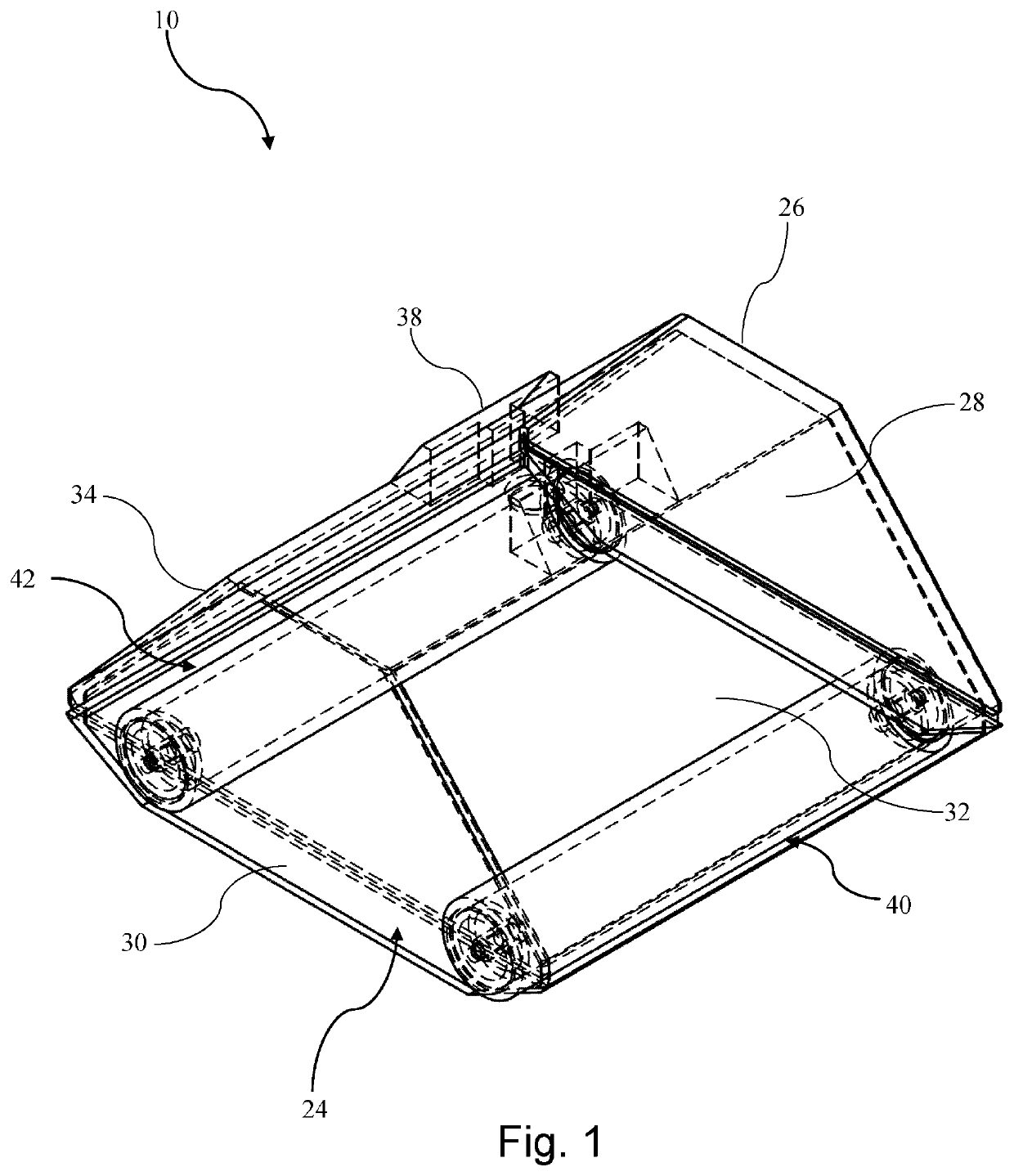
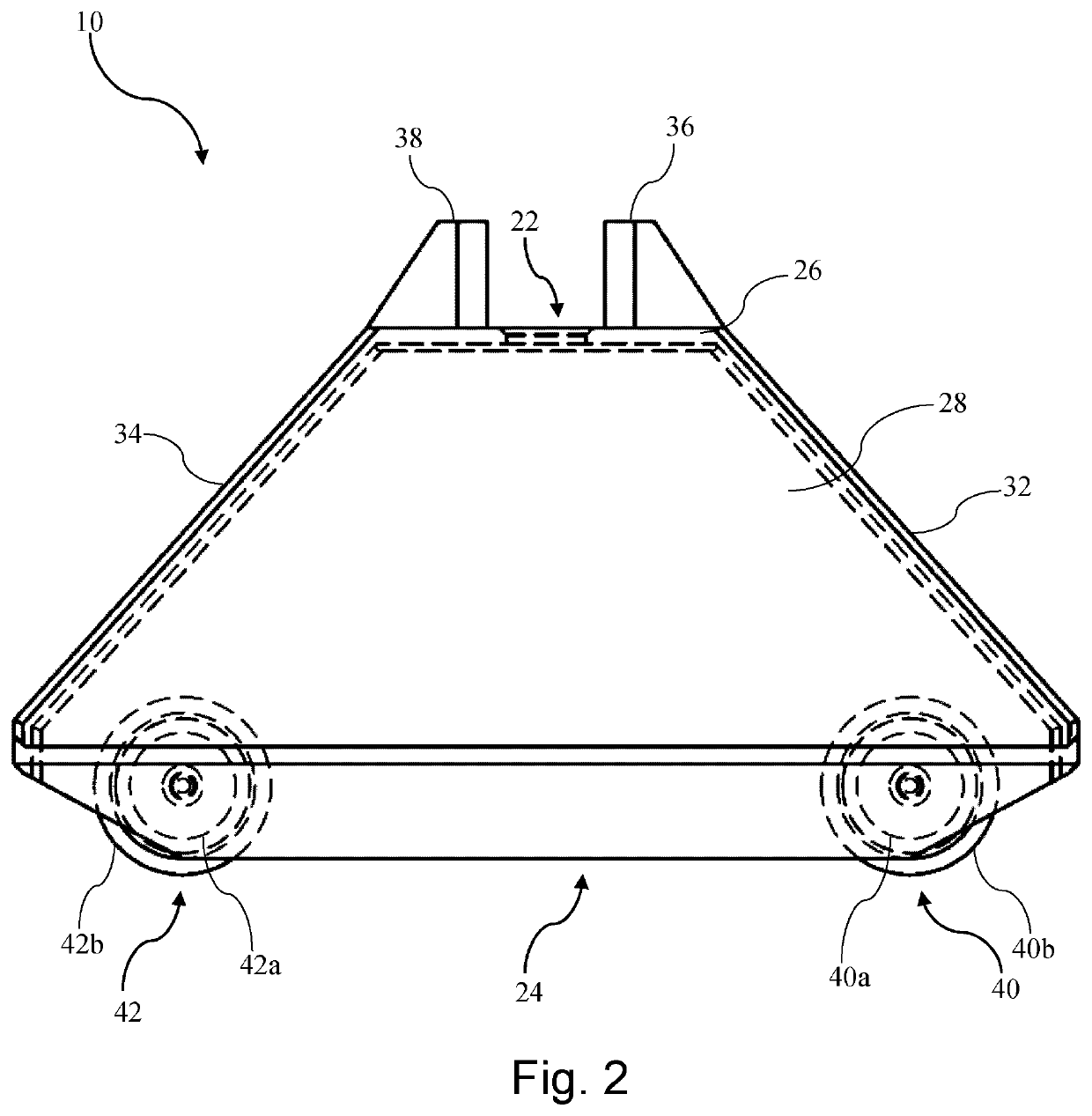
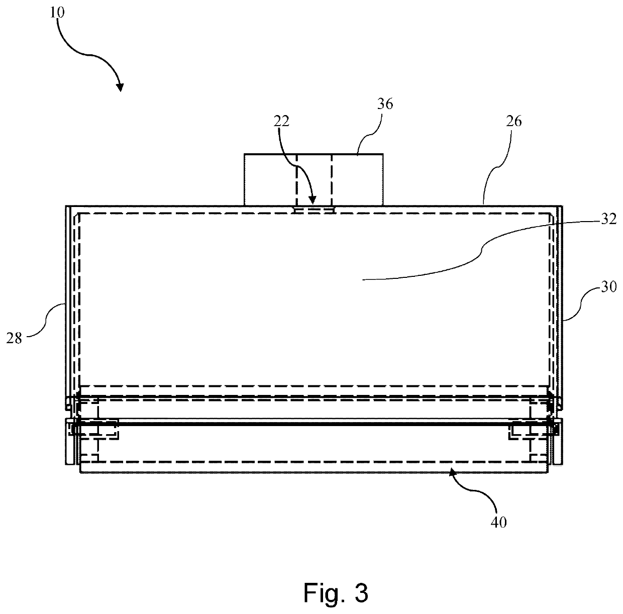
[0054]FIGS. 1 to 9 show an embodiment of a painting device 10. The painting device 10 comprises a shroud 20 formed from a carbon fibre composite. It will be appreciated that, in other embodiments, the shroud 20 may be formed from any other suitable rigid material, such as a rigid polymer.

[0055]As best seen in FIGS. 5 to 8, the shroud 20 has an interior with an inlet opening 22 and an opposing outlet opening 24. The shroud 20 comprises a top wall 26, a pair of lateral side walls 28, 30, a front wall 32, and a rear wall 34. The top wall 26 is substantially planar and rectangular in shape defined by front and rear longitudinal sides, and right and left side ends. The top wall 26 has a central circular aperture which defines the inlet opening 22. Each of the lateral side walls 28, 30 is substantially planar and trapezoidal in shape. The side walls 28, 30 extend substantially parallel to each other. The side wall 28 extends downwardly from the left side end of the top wall 26 to the outl...


PUM


Abstract

A painting device (10) for a paint sprayer (102) with a spray gun and a nozzle (110) connected to the spray gun. The painting device (10) comprises: a shroud (20) for shielding the nozzle of the paint sprayer, the shroud (20) having an inlet opening (22) for locating the nozzle in an interior of the shroud and an opposing outlet opening (24) for applying paint to a surface to be painted; and roller means (40, 42) mounted on or attached to the shroud (20), the roller means being configured to engage with the surface to be painted for supporting the shroud of the painting device for rolling movement over the surface with the outlet opening positioned substantially adjacent to the surface to be painted. The shroud (20) is configured for attachment of the paint sprayer (102) such that the spray gun connects to the nozzle (110) at or through the inlet opening (22) and the nozzle is fixed in the interior to substantially direct paint sprayed therefrom through the outlet opening (24). Also provided is a painting apparatus (100) comprising a painting device (10) and a paint sprayer (102). The shroud (20) of the painting device (10) is attached to the paint sprayer (102) such that the spray gun connects to the nozzle (110) through the inlet opening (22) and the nozzle (110) is fixed in the interior to substantially direct paint sprayed therefrom through the outlet opening (24).

Description

FIELD[0001]The present invention relates to a painting device and a painting apparatus.BACKGROUND[0002]Hand-held paint rollers are commonly used in painting surfaces. Generally, a hand-held paint roller comprises a handle, a frame extending from the handle to define a shaft, and a paint applicator rotatably attached to the shaft. The paint applicator is generally formed from a cylindrical core encased by a synthetic foam cover.[0003]In one known method of painting, the paint applicator of a hand-held paint roller is dipped into paint contained in a tray. The paint applicator is then manually pressed and rolled against the tray to evenly absorb the paint. The paint applicator is then manually pressed and rolled against a surface to apply the paint. Although hand-held paint rollers can provide a consistent finish, the use of hand-held paint rollers is often very labour intensive and time consuming, especially when painting large surfaces. Also, paint can often drip from the paint appl...

Claims


Application Information

Patent Timeline
Patent Type & Authority Applications(United States)
IPC IPC(8): B05B1/28B05B9/01B05B9/00B05D1/02
CPCB05B9/01B05B1/28B05B9/007B05D1/02B05B9/0403B05B14/30B05B12/22B05B12/32
Inventor SMITH, MARK NICHOLASCANALES, RODRIGO HIDALGOROSBERGEN, JORDY SVEN
Owner CPR GRP AUSTRALIA PTY LTD
Learn More