Gas Turbine and the Method of Controlling Bleed Air Volume for Gas Turbine
- Summary
- Abstract
- Description
- Claims
- Application Information
AI Technical Summary
Benefits of technology
Problems solved by technology
Method used
Image


Examples
first embodiment
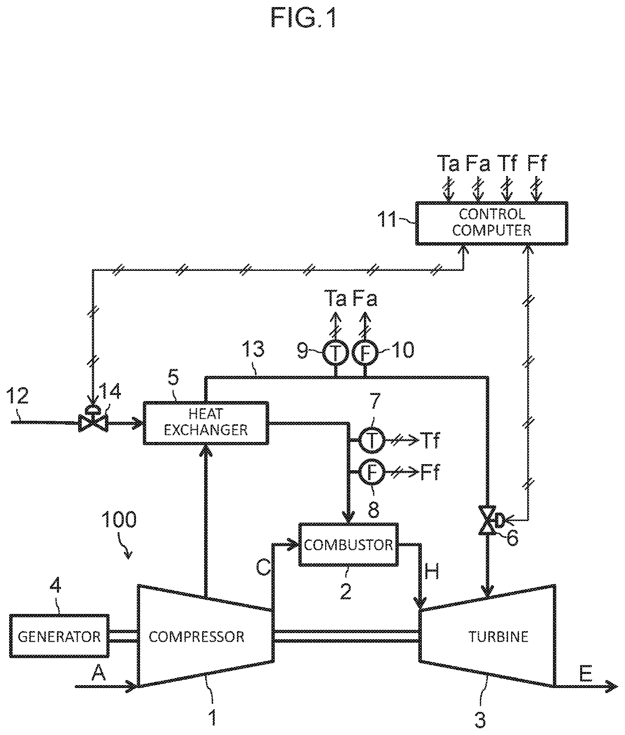
[0014]—Gas Turbine—
[0015]FIG. 1 is a schematic diagram of an example of a gas turbine according to a first embodiment of the present invention. In the present embodiment, a gas turbine combustor is referred to simply as a combustor. A gas turbine 100 illustrated in FIG. 1 includes a compressor 1, a combustor 2, a turbine 3, load equipment 4, a heat exchanger 5, a bleed valve 6, first sensors 7 and 8, second sensors 9 and 10, and a control computer 11.
[0016]The compressor 1 compresses an air A sucked in through an air inlet to generate and discharge a high-pressure compressed air C. The combustor 2 burns a fuel mixed with the compressed air C compressed by the compressor 1 to generate a high-temperature combustion gas H, and supplies the combustion gas H to the turbine 3. The turbine 3 is driven by the combustion gas H generated by the combustor 2. The compressor 1 and the turbine 3 are coaxially connected, and the load equipment 4, e.g., a generator or a pump, is connected to the co...
second embodiment
[0031]FIG. 4 is a flowchart illustrating a procedure of controlling a bleed valve of a gas turbine according to the second embodiment of the present invention. FIG. 5 is a model diagram illustrating changes over time of a fuel state value and a cooling air state value for explaining timing of control of the bleed valve in the gas turbine according to the second embodiment of the present invention. FIGS. 4 and 5 correspond to FIGS. 2 and 3, respectively. The present embodiment is different from the first embodiment in that the control of changing the degree of opening of the bleed valve 6 is performed only when both the fuel state value a and the cooling air state value b have fallen outside of the corresponding dead bands, and is similar in hardware configuration to the first embodiment.
[0032]After loading the program into the CPU and starting the control illustrated in FIG. 4, the control computer 11 receives input of measurement signals from the first sensors 7 and 8 and the secon...
PUM
 Abstract
Description
Claims
Application Information