Safety system and method for power tools

Active Publication Date: 2020-05-21
LEWIS DENNIS E
View PDF9 Cites 2 Cited by
  • Summary
  • Abstract
  • Description
  • Claims
  • Application Information

AI Technical Summary

Benefits of technology

The present invention is a safety system and method for power tools that stops the blade of a power tool upon skin contact without damaging or destroying the blade. The safety system is inexpensive to implement, easy to test and can be retrofit onto existing power tools. Its technical effects include increased safety for power tool users and reduced likelihood of injury or damage caused by accidental skin contact.

Problems solved by technology

Power equipment such as table saws, circular saws, radial arm saws, miter saws and other machinery for cutting, drilling, sawing, or otherwise modifying workpieces made from various materials include cutting implements such as circular saw blades and knife blades that present a risk of injury to a user of such equipment.
In particular, these implements, often rotating at high speed, can inflict significant damage to the human body if it inadvertently comes in contact with such implements.
While these features have certainly reduced the number of blade contacts, there are many situations where the nature of the equipment and the operations to be performed using such equipment preclude using a guard that obstructs access to rotating cutting implements.
These existing systems, however, may interfere with smooth operation of the machine, such as by interrupting operation where a blade-contact event is unlikely.
Moreover, many existing systems use destructive blade contact to stop rotation of the saw blade, which can damage the blade or machine.
If a human contacts the blade, the signal will fall below a threshold, and after a predetermined time, destructive blade contact will be deployed to stop the blade.
This method of detecting human body contact, however, is complex and adds additional cost to the machine, and uses a fusible link and aluminum blade grabber that are sacrificed when stopping rotation of the blade.

Method used


Image

  • Safety system and method for power tools
  • Safety system and method for power tools

Examples


Embodiment Construction

[0018]Reference will be made below in detail to exemplary embodiments of the invention, examples of which are illustrated in the accompanying drawings. Wherever possible, the same reference characters used throughout the drawings refer to the same or like parts, without duplicative description.

[0019]As used herein, the terms “substantially,”“generally,” and “about” indicate conditions within reasonably achievable manufacturing and assembly tolerances, relative to ideal desired conditions suitable for achieving the functional purpose of a component or assembly. As used herein, “electrically coupled”, “electrically connected” and “electrical communication” means that the referenced elements are directly or indirectly connected such that an electrical current may flow from one to the other. Such connections may include a direct conductive connection (i.e., without an intervening capacitive, inductive or active element), an inductive connection, a capacitive connection, and / or any other...


PUM


Abstract

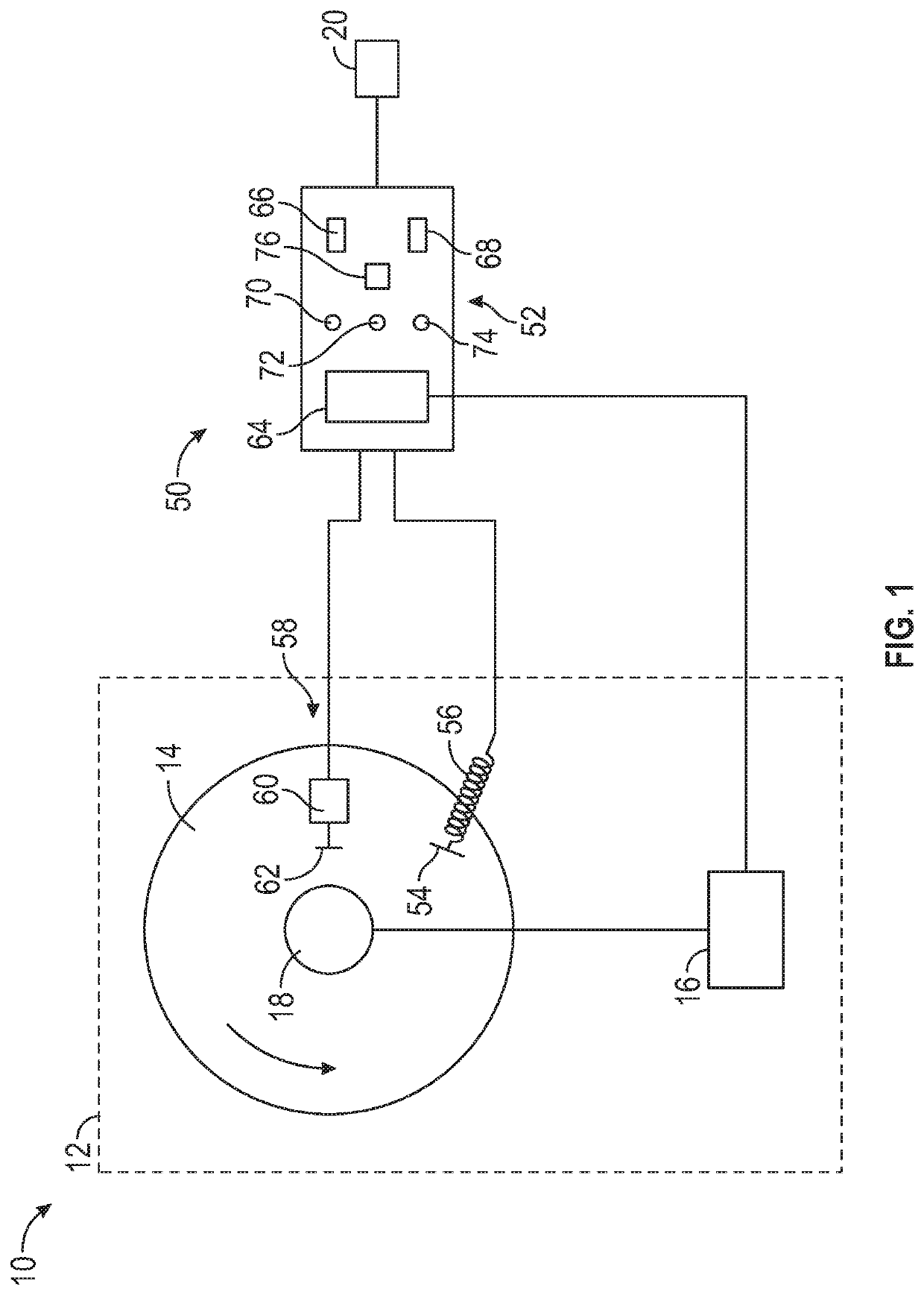
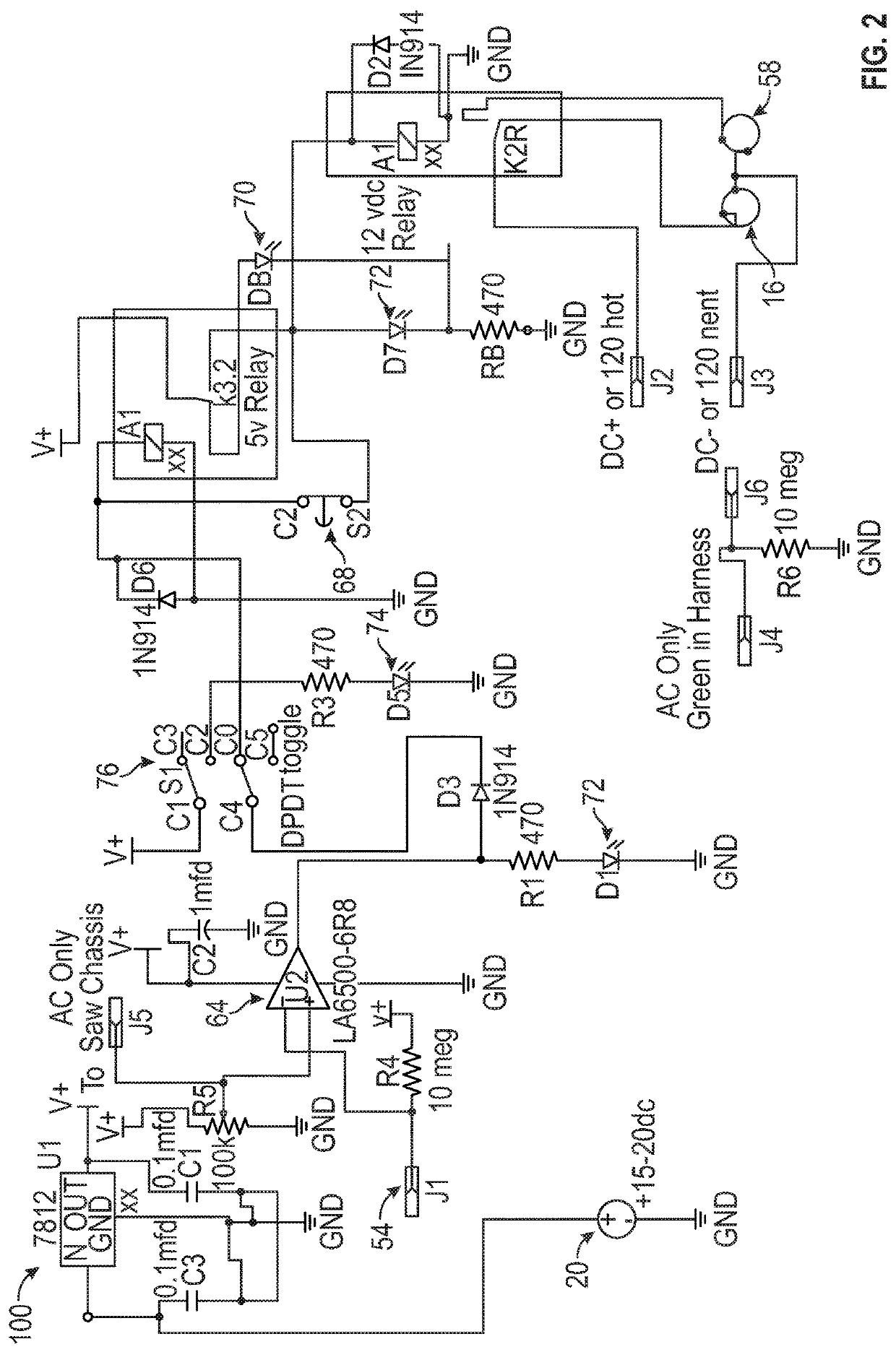
A safety system for a power tool having a motor and a cutting tool driven by the motor includes a control device configured to detect a direct contact of a conductive material with the cutting tool, the direct contact of the conductive material with the cutting tool defining a contact event, and a braking device movable between a retracted position and an engaged position. The control device is configured to interrupt electrical power to the motor and control the braking device to the engaged position when the contact event is detected.

Description

FIELD OF THE INVENTION[0001]The present invention relates generally to electric devices and, more particularly, to a system and method for improving the safety of power equipment such as saws having rotating blades.BACKGROUND OF THE INVENTION[0002]Power equipment such as table saws, circular saws, radial arm saws, miter saws and other machinery for cutting, drilling, sawing, or otherwise modifying workpieces made from various materials include cutting implements such as circular saw blades and knife blades that present a risk of injury to a user of such equipment. In particular, these implements, often rotating at high speed, can inflict significant damage to the human body if it inadvertently comes in contact with such implements. In view of this risk, various safety systems and features have been heretofore incorporated into power equipment to minimize the risk of injury. For example, table saws, miter saws and circular saws are often outfitted with various blade guards, fences an...

Claims


Application Information

Patent Timeline
IPC IPC(8): F16P3/12H02K7/14H02K11/28H02K11/26
CPCB27B13/14B27G21/00H02K11/28F16P3/12B27B5/38B27G19/06B27G19/02H02K11/26H02K7/14
Inventor LEWIS, DENNIS E.
Owner LEWIS DENNIS E
Why Eureka
Try Eureka