Layer debonding

a technology of layer debonding and composite blades, applied in the direction of efficient propulsion technologies, machines/engines, manufacturing tools, etc., can solve the problems of metal-composite interface debonding of composite blades, blade tips touching the nacelle, need for replacement, etc., to facilitate heat transfer, increase the thermal conductivity of the first layer, and facilitate the effect of heat transfer

Active Publication Date: 2020-05-28
ROLLS ROYCE PLC
View PDF1 Cites 1 Cited by
  • Summary
  • Abstract
  • Description
  • Claims
  • Application Information

AI Technical Summary

Benefits of technology

[0015]The speed of movement of the cleaving tool therefore reduces, optionally / in some cases to zero (i.e. a dwell or pause), when the force required for movement is greater than the calculated de-bonding force, so as to allow time for the adhesive in the region to weaken (e.g. softening on being heated).
[0124]The heating component may be mounted on the tool forward of the blade (in an intended direction of movement of the tool) such that a portion of the adhesive is heated before the blade reaches that portion. The skilled person will appreciate that the pre-heating may facilitate debonding by softening the adhesive and so reducing the minimum required debonding force.

Problems solved by technology

This may result in blade tips touching the nacelle—i.e. tip rub.
In the event of tip rub, the metal-composite interface of the composite blade may debond due to the resultant high temperatures.
Impacts on the blades from foreign bodies may also cause damage and result in a need for replacement.
However, the leading edge metalwork (often titanium) is normally significantly thicker and normally has a wider bonded width, making the peel force higher and manual removal harder or impossible.

Method used


Image

  • Layer debonding
  • Layer debonding
  • Layer debonding

Examples


Embodiment Construction

[0179]In the figures, like reference numerals are used for like components.

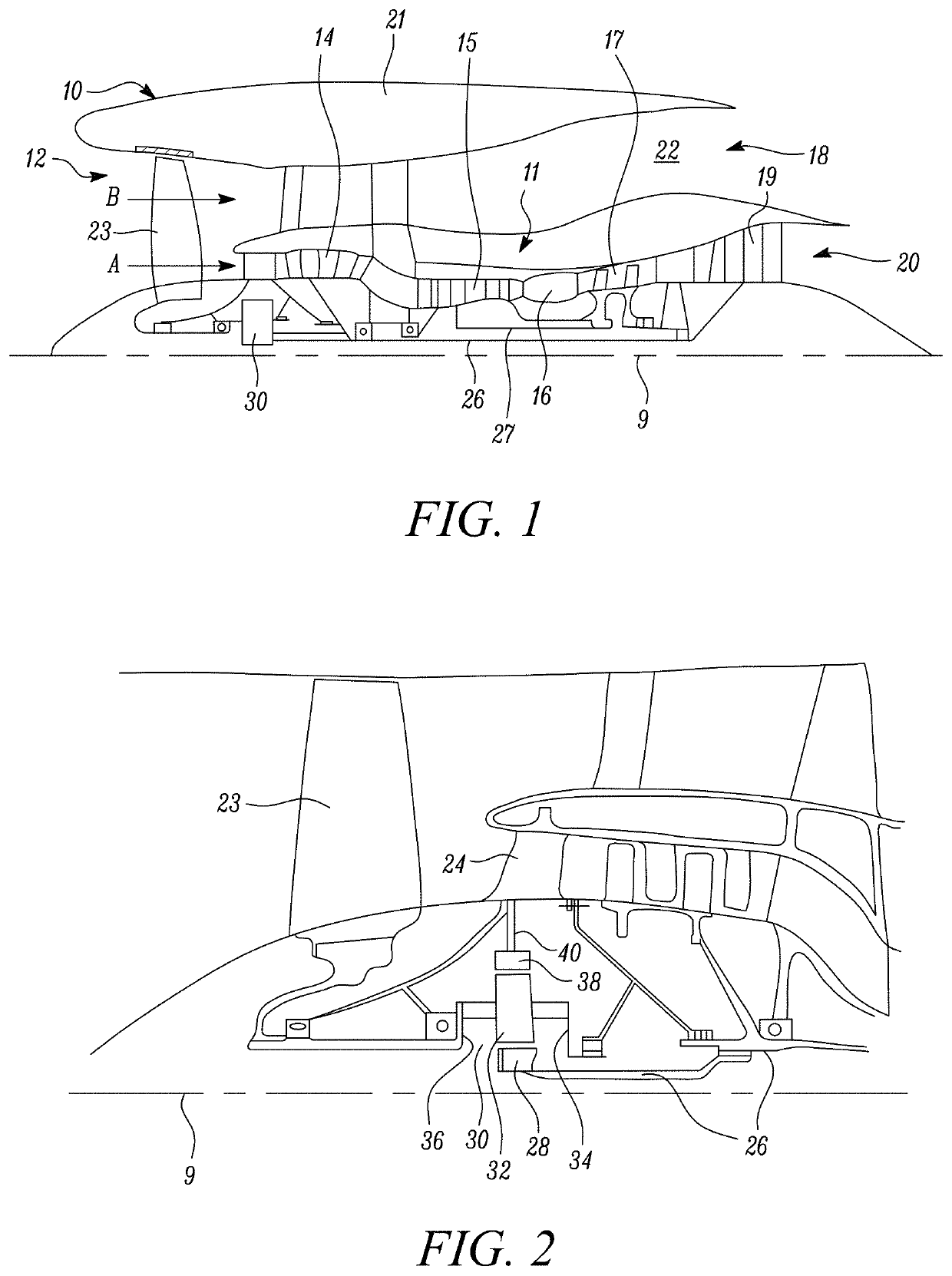
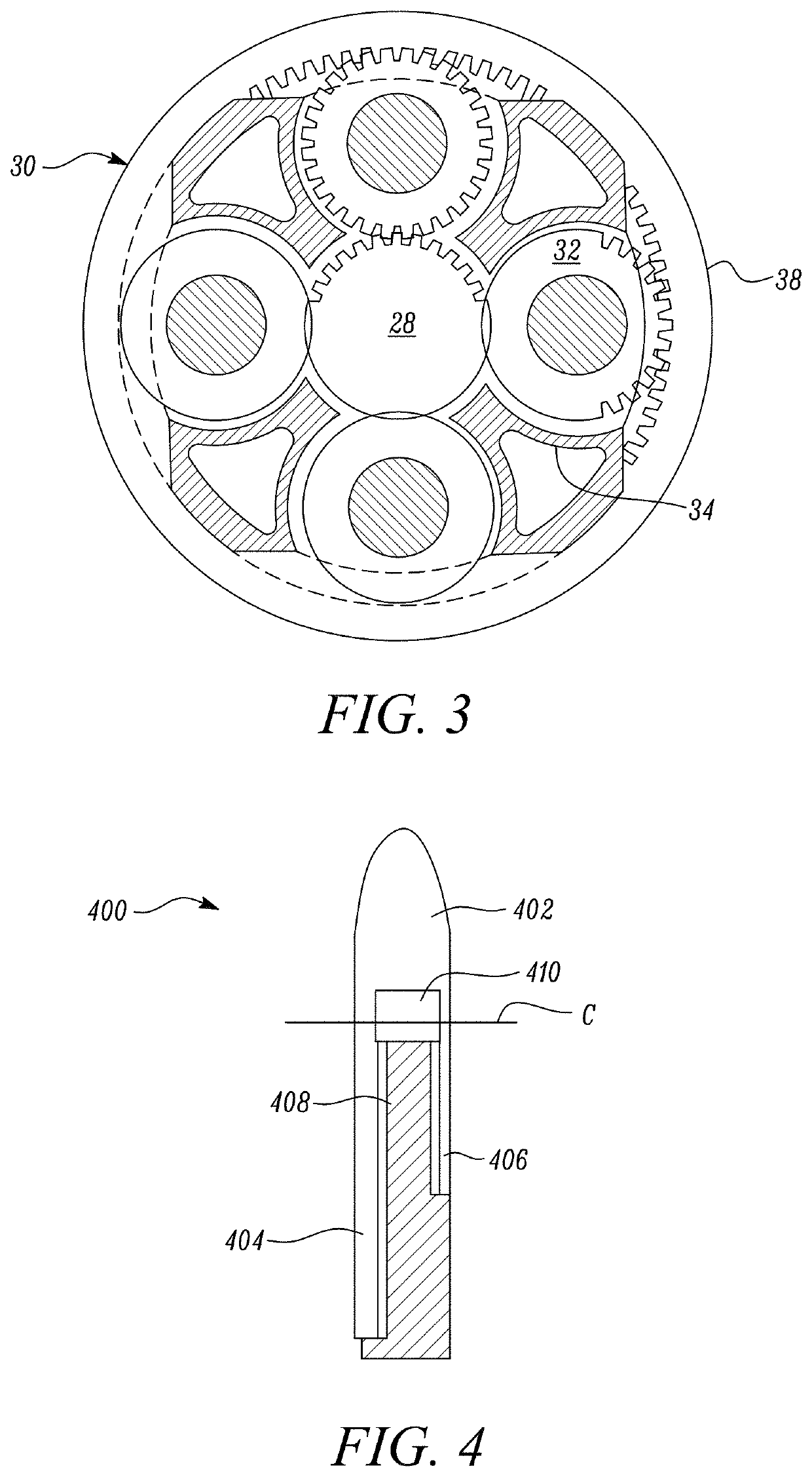
[0180]FIG. 1 illustrates a gas turbine engine 10 having a principal rotational axis 9. The engine 10 comprises an air intake 12 and a propulsive fan 23 that generates two airflows: a core airflow A and a bypass airflow B. The gas turbine engine 10 comprises a core 11 that receives the core airflow A. The engine core 11 comprises, in axial flow series, a low pressure compressor 14, a high-pressure compressor 15, combustion equipment 16, a high-pressure turbine 17, a low pressure turbine 19 and a core exhaust nozzle 20. A nacelle 21 sur-rounds the gas turbine engine 10 and defines a bypass duct 22 and a bypass exhaust nozzle 18. The bypass airflow B flows through the bypass duct 22. The fan 23 is attached to and driven by the low pressure turbine 19 via a shaft 26 and an epicyclic gearbox 30.

[0181]In use, the core airflow A is accelerated and compressed by the low pressure compressor 14 and directed into the hi...


PUM

PropertyMeasurementUnit
angleaaaaaaaaaa
angleaaaaaaaaaa
angleaaaaaaaaaa

Abstract

A method (1800) of debonding a first layer (404) from a second layer (408), wherein the first layer (404) is bonded to the second layer (408) by an adhesive (410) located between the first and second layers, comprises: inserting (1804) a blade (602) of a cleaving tool (600) between the first and second layers (404, 408); and exerting (1806) a controlled force on the cleaving tool (600) to move the cleaving tool so as to de-bond the first and second layers (404, 408) in a region, wherein the force exerted is controlled to match a de-bonding force calculated for the region, and such that the movement of the cleaving tool (600) stops if the calculated force is less than force required to move the cleaving tool (600) and continued if the calculated force is higher than or equal to the force required to move the cleaving tool.

Description

CROSS-REFERENCE TO RELATED APPLICATIONS[0001]This specification is based upon and claims the benefit of priority from UK Patent Application Number 1819249.2 filed on Nov. 27, 2018, the entire contents of which are incorporated herein by reference.BACKGROUND1. Field of the Disclosure[0002]The present disclosure relates to tools and methods for debonding a first layer from a second layer to which the first layer is adhered with a bonding substance such as an adhesive. The first layer may be metallic and the second layer may be polymeric, for example a carbon fibre reinforced polymer. In particular, but not exclusively, the disclosure relates to the separation of metalwork from a carbon fibre reinforced polymer (CFRP), which may be of utility for repair or recycling of composite fan blades such as blades from fans of aircraft gas turbine engines.2. Description of the Related Art[0003]The skilled person will appreciate that clearances between fan blade tips and an inner surface of a nac...

Claims


Application Information

Patent Timeline
Patent Type & Authority Applications(United States)
IPC IPC(8): B32B43/00B26D3/28
CPCB32B43/006B32B2603/00B26D3/28B23P19/04F01D5/005B29C63/0013B23P6/002B23P15/04B29L2031/082B29L2031/7504F05D2220/36F05D2230/80F05D2300/6032F05D2300/603F05D2240/303B29C73/26B29C2073/264Y02T50/60
Inventor NG, WU XIN CHARLESVADUGAPPATTY SRINIVASAN, DHARUNAGGARWAL, ATINIDAPALAPATI, SRIDHAR
Owner ROLLS ROYCE PLC
Why Eureka
Try Eureka