Chemiluminescence detector sample enclosure

Pending Publication Date: 2020-05-28
RANDOX LAB LTD
View PDF0 Cites 0 Cited by
  • Summary
  • Abstract
  • Description
  • Claims
  • Application Information

AI Technical Summary

Benefits of technology

[0024]As with the first sealing element, the second sealing element may be any device suitable for forming a light restricting seal with another body. Typically, the second sealing element comprises a plurality of concentric ridges. This allows the seal produced by the first and second sealing members to form a labyrinth through which any light must travel to cross the seal. This improves the light restricting ability of the seal.
[0025]Preferably, when the first interface member is engaged with each respective sample holder, the gasket may be configured to deform around each ridge of the concentric ridges of the second sealing element thereby providing co

Problems solved by technology

This makes it difficult to detect under ordinary room lighting, meaning that a number of step are taken to allow suitable detection of chemiluminescence.
However, providing a suitable container is difficult, especially when multiple discrete microarrays are to be analysed.
This is because the equipment needed to conduct the analysis takes up a large amount of space due to the need for components to move the microarrays between each stage of the analysis process and the components required to carry out steps in the analysis process, such as to add substances to each microarray.
Maintaining sufficiently low light levels in such a large space is difficult

Method used


Image

  • Chemiluminescence detector sample enclosure
  • Chemiluminescence detector sample enclosure
  • Chemiluminescence detector sample enclosure

Examples


Example

[0034]We now describe an example of a chemiluminescence detector sample enclosure including an example cartridge and movement mechanism. A process by which chemiluminescence is able to be detected is also described.

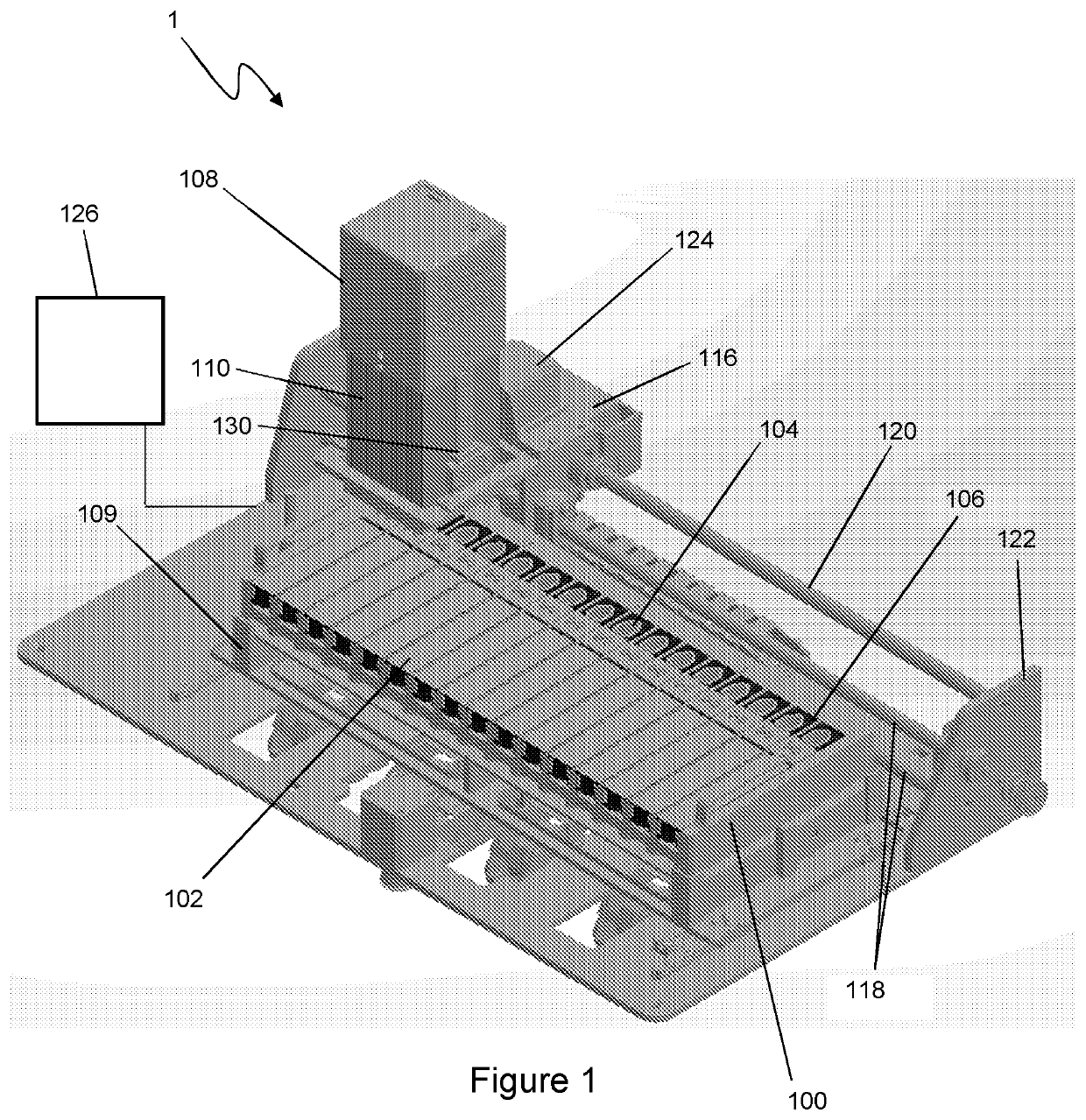
[0035]Referring now to FIG. 1, a chemiluminescence detector sample enclosure is generally illustrated at 1. The enclosure forms part of an analyser (not shown) that is used to analyse a number of samples and carry out a number of test at the same time. Indeed, detection of chemiluminescence is only one step on the analysis that is carried out using the enclosure and its components.

[0036]The enclosure 1 has a rack 100 into which a plurality of cartridges 102 are secured. Each cartridge is clipped into the rack in order to hold it securely in the rack. The cartridges are positioned so that their length runs across the width of the rack with the cartridges arranged side by side so that they are adjacent each other.

[0037]Each cartridge 102 is a consumable item that it is inte...


PUM


Abstract

There is provided a chemiluminescence detector sample enclosure. The enclosure comprises a first interface member forming part of a chemiluminescence detector and having a first sealing element and a second interface member comprising a plurality of sample holders, each sample holder having a second sealing element. The first interface member is engagable with and moveable between sample holder subsets of the plurality of sample holders, engagement with a respective sample holder subset providing engagement of the first interface member with each sample holder of the respective sample holder subset and relative movement of the first and second interface members providing movement between sample holder subsets; and when the first interface member is engaged with each respective sample holder, the first sealing element and the respective second sealing element are adapted to interact so as to form a light restricting seal between the first interface member and said sample holder.

Description

FIELD OF THE INVENTION[0001]The present invention relates to an enclosure used in chemiluminescence detection and restriction of light ingress at an interface between a sample holder and a detector.BACKGROUND[0002]There are many occasions where there is a desire to conduct analysis on a liquid sample, or the constituents of a liquid sample. This is achievable by measuring one or more properties of such an analyte, such as measuring a glucose concentration in a liquid sample.[0003]For such analysis and testing to be industrially viable, measurements are commonly carried out on multiple analytes simultaneously. This is known as multianalyte analysis.[0004]Usually, only a small quantity of each analyte is measured. This is because either it is desirable or only possible to analyse a small amount of each analyte, or many tests are to be carried out on a single analyte that is divided into a number of specimens to enable discrete testing to be applied to each specimen. This means that ea...

Claims


Application Information

Patent Timeline
IPC IPC(8): G01N21/76B01L3/00
CPCB01L2200/0689B01L3/50855B01L2200/02G01N21/76B01L3/5085G01N21/64G01N35/02B01L2300/168
Inventor WHARRY, MARCEVANS, P.JACKSON, STUART
Owner RANDOX LAB LTD
Why Eureka
Try Eureka