Eureka AIR delivers breakthrough ideas for toughest innovation challenges, trusted by R&D personnel around the world.

Bipolar plate for use in an electrochemical device

a bipolar plate and electrochemical technology, applied in the direction of electrolysis components, electrochemical generators, transportation hydrogen technology, etc., can solve the problem that the electrochemical device cannot be cooled either via the supply water, and achieve the effects of low weight, excellent heat transmission, and efficient cooling

Active Publication Date: 2020-05-28
AIRBUS DEFENCE & SPACE
View PDF0 Cites 0 Cited by
  • Summary
  • Abstract
  • Description
  • Claims
  • Application Information

AI Technical Summary

Benefits of technology

[0014]Overall, an excellent transmission of heat and therefore efficient cooling can be carried out by the bipolar plate according to the disclosure even in electrolysis cells in a matrix construction. A particularly compact construction with a low weight for an electrolysis device or another electrochemical device can therefore be realized.
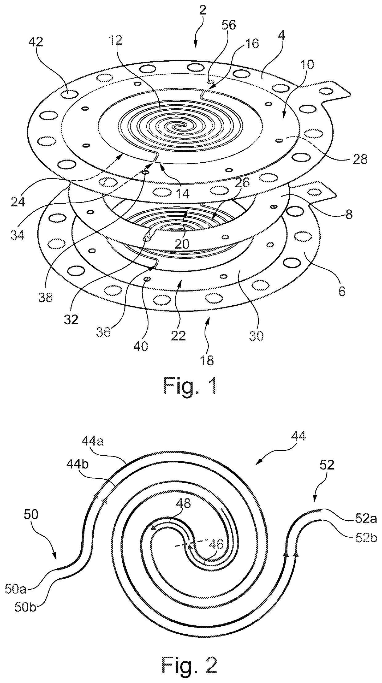
[0015]In a preferred embodiment, the at least one flow duct extends spirally at least in regions in the intermediate space. The spiral shape leads to an improved utilization of the available area in the intermediate space and therefore to an improved cooling effect when a coolant flows through the flow duct.
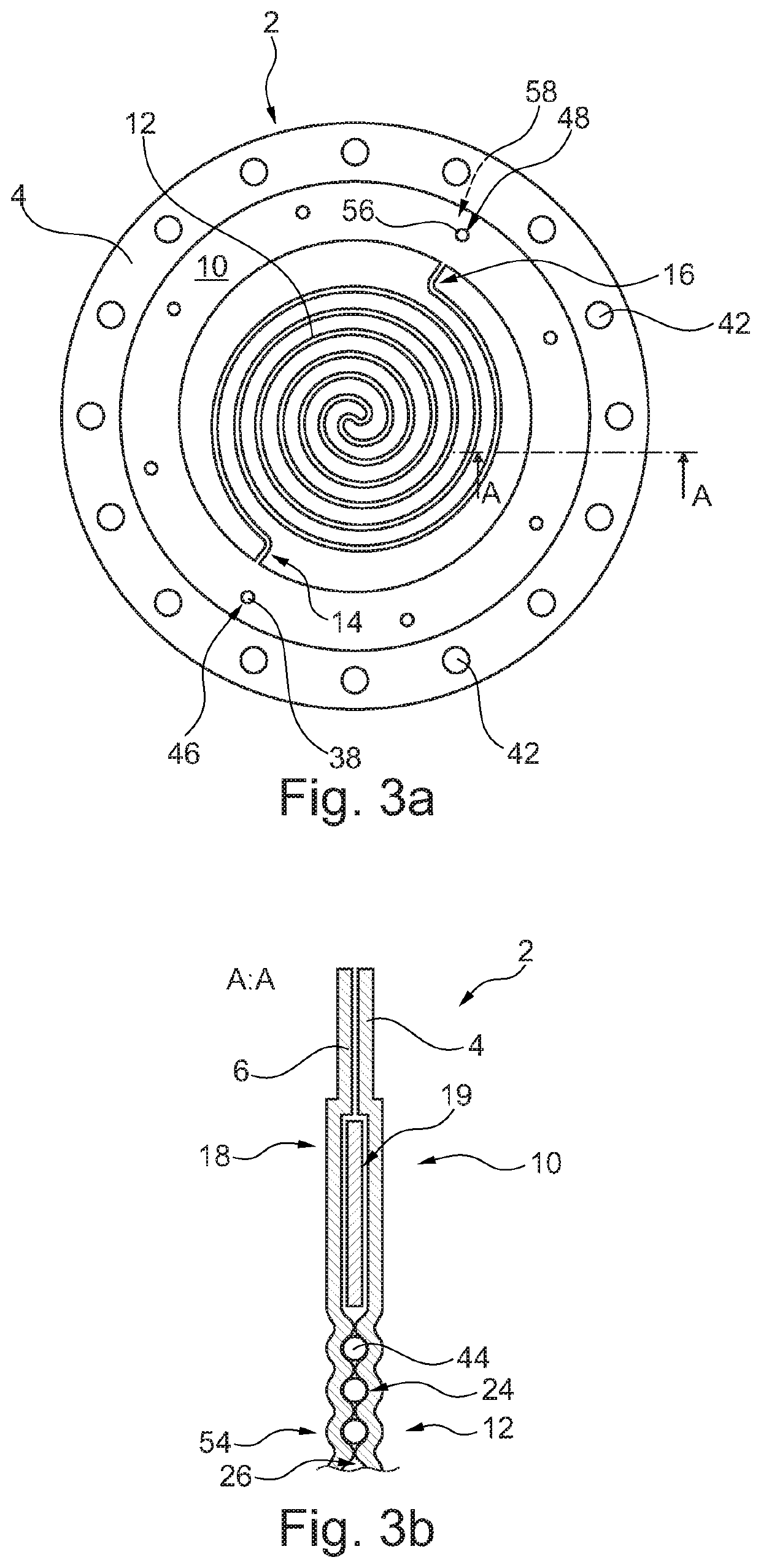
[0016]In an advantageous embodiment, the at least one flow duct has a first strand and an adjoining second strand, wherein the first strand is curved in a first direction and the second strand in an opposite second direction. The first strand could consequently be designed in such a manner that the extent formed by the first strand becomes continuously smaller. The first strand could therefore extend from a radially outer region of the intermediate space in the direction of a radially further inner region. In this case, the first strand could run radially inwards to an extent possible taking into consideration the heat dissipation and the curvature which can be realized of the flow duct. In the meantime, the second strand could adjoin the first strand in such a manner that it extends spirally from a radially inner region to a radially further outer region. The p

Problems solved by technology

In some cases, such an electrolyser cannot be cooled

Method used


Image

  • Bipolar plate for use in an electrochemical device
  • Bipolar plate for use in an electrochemical device
  • Bipolar plate for use in an electrochemical device

Examples


Embodiment Construction

[0038]The following detailed description is merely illustrative in nature and is not intended to limit the embodiments of the subject matter or the application and uses of such embodiments. As used herein, the word “exemplary” means “serving as an example, instance, or illustration.” Any implementation described herein as exemplary is not necessarily to be construed as preferred or advantageous over other implementations. Furthermore, there is no intention to be bound by any expressed or implied theory presented in the preceding technical field, background, brief summary or the following detailed description.

[0039]FIG. 1 shows an exemplary construction of a bipolar plate 2 in an exploded illustration. The bipolar plate 2 has a first plate like component 4, a second plate like component 6 and an intermediate ring 8. These three components are produced in particular from a metallic material in order to be able to provide sufficient electron conductivity. They can preferably be welded ...


PUM


Abstract

A bipolar plate for use in an electrochemical device is proposed, in which a flow duct runs between two outer boundary surfaces and extends from a peripheral fluid inlet to a peripheral fluid outlet. As a result, very good cooling of electrochemical cells via a bipolar plate which is in surface contact therewith can be achieved.

Description

CROSS-REFERENCE TO PRIORITY APPLICATION[0001]This application claims the benefit of, and priority to, German patent application number 102018129887.0, filed Nov. 27, 2018. The content of the referenced application is incorporated by reference herein.TECHNICAL FIELD[0002]Embodiments of the subject matter described herein relate generally to a bipolar plate for use in an electrochemical device. The disclosure further relates to an electrochemical device and to a vehicle, in particular an aircraft or a space vehicle, with such an electrochemical device.BACKGROUND[0003]An electrochemical device within the meaning of the disclosure can be, for example, an electrolyser with which propulsion materials for a spacecraft or other systems can be generated. An electrolyser could, for example, periodically decompose water into hydrogen and oxygen. For this purpose, at least one electrolysis cell can be provided, with different constructional forms being known for the realization thereof.[0004]Al...

Claims


Application Information

Patent Timeline
IPC IPC(8): H01M8/04029H01M8/04007H01M8/0267H01M8/0258
CPCH01M2250/20H01M8/0258H01M8/04074H01M8/0267H01M8/04029Y02E60/36Y02E60/50C25B1/04Y02T90/40C25B9/75C25B9/67C25B11/036
Inventor ECK, THOMASJEHLE, WALTERLOHMILLER, WINFRIED
Owner AIRBUS DEFENCE & SPACE
Why Eureka
Eureka Blog
Learn More