
Projection control apparatus, control method of the same, and projection system

a technology of projection control and control method, applied in the direction of electrical apparatus, picture reproducers using projection devices, color television details, etc., can solve the problem that the technique cannot be applied in the cas

Inactive Publication Date: 2020-05-28
CANON KK
View PDF0 Cites 5 Cited by
  • Summary
  • Abstract
  • Description
  • Claims
  • Application Information

AI Technical Summary

Benefits of technology

The invention provides a device and method to control projections from multiple projectors. Its technical effect is that it makes it easy to adjust the positions of the projectors, even if they are not perfectly aligned.

Problems solved by technology

This technique therefore cannot be applied in the case where none of the projectors have already been aligned.

Method used


Image

  • Projection control apparatus, control method of the same, and projection system
  • Projection control apparatus, control method of the same, and projection system
  • Projection control apparatus, control method of the same, and projection system

Examples


first embodiment

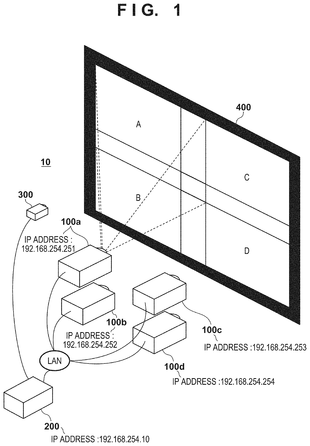
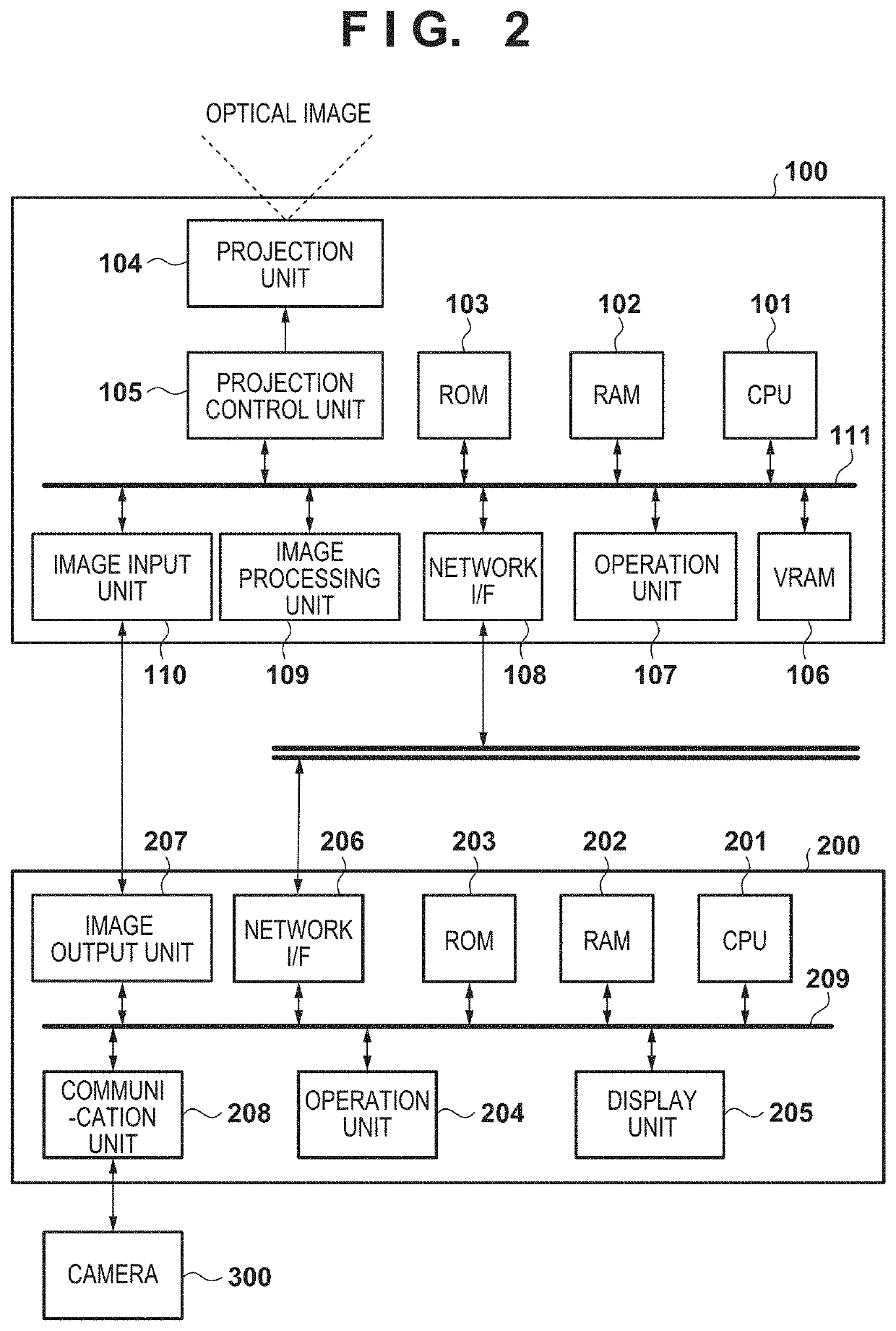
[0023]Exemplary embodiments of the present invention will now be described in detail in accordance with the accompanying drawings. Note that the present invention is not intended to be limited to the embodiments described below. Also, the constituent elements described in the embodiments are not all necessarily essential to the present invention. Individual function blocks in the embodiments can be realized by hardware, software, or a combination of hardware and software. Also, an individual function block may be realized by multiple pieces of hardware. Moreover, an individual piece of hardware may be realized by multiple function blocks. Furthermore, one or more function blocks may be realized by one or more programmable processors (CPU, MPU, etc.) executing a computer program that has been loaded to a memory. When one or more function blocks are realized by hardware, such hardware can be a discrete circuit or an integrated circuit such as an FPGA or an ASIC.

[0024]Also, the graphic...

second embodiment

[0150]Next, a second embodiment of the present invention will be described. The present embodiment describes processing in the case where a projector that can project the assist markers is not found. Portions of the configuration of the projection system, the automatic alignment processing overview, the GUI screens of the automatic alignment application, and the like that are the same as in the first embodiment will not be described. FIG. 12 is a flowchart of installation assistance processing in the present embodiment. The processing of steps S901 to S908 is similar to that in the first embodiment, and therefore will not be described.

[0151]In step S1201, the CPU 201 determines whether or not a projector that can project assist markers for a projector targeted for installation position adjustment could be determined in step S908. For example, the CPU 201 moves to step S909 if it is determined that a marker projection projector could be determined for all of the markers, and moves to...


PUM


Abstract

A projection control apparatus for controlling projection performed using projectors is disclosed. The control apparatus, for each of the projectors, detects a projection area, being on a projection surface, in which an optical image is projected, based on a captured image of the projection surface. The control apparatus then causes an indicator indicating a target projection area for one of the projectors to be displayed by one or more other projectors. The control apparatus finally determines a projector that is to project the indicator from among the one or more other projectors based on a detection result of the detection.

Description

BACKGROUND OF THE INVENTIONField of the Invention[0001]The present invention relates to a projection control apparatus, a control method of the same, and a projection system, and particularly relates to a technique for adjusting a projection position.Description of the Related Art[0002]A method of performing projection with use of multiple projectors (sometimes referred to as “multi-projection”) is known. In multi-projection, the projection position of each projector needs to be adjusted (aligned) individually, and therefore projectors that have a function for facilitating alignment are also known.[0003]Japanese Patent Laid-Open No. 2015-121779 discloses a technique for facilitating the correction of the installation positions of projectors by using a projector that has already been aligned to project a reference image for correcting the installation positions of projectors that have not been aligned.[0004]With the technique disclosed in Japanese Patent Laid-Open No, 2015-121779, at...

Claims


Application Information

Patent Timeline
Patent Type & Authority Applications(United States)
IPC IPC(8): H04N9/31
CPCH04N9/3185H04N9/3147H04N9/3194
Inventor MORI, MAKIKO
Owner CANON KK
Learn More