
Dental Implant Framework

Active Publication Date: 2020-06-04
CAGENIX
View PDF0 Cites 4 Cited by
  • Summary
  • Abstract
  • Description
  • Claims
  • Application Information

AI Technical Summary

Benefits of technology

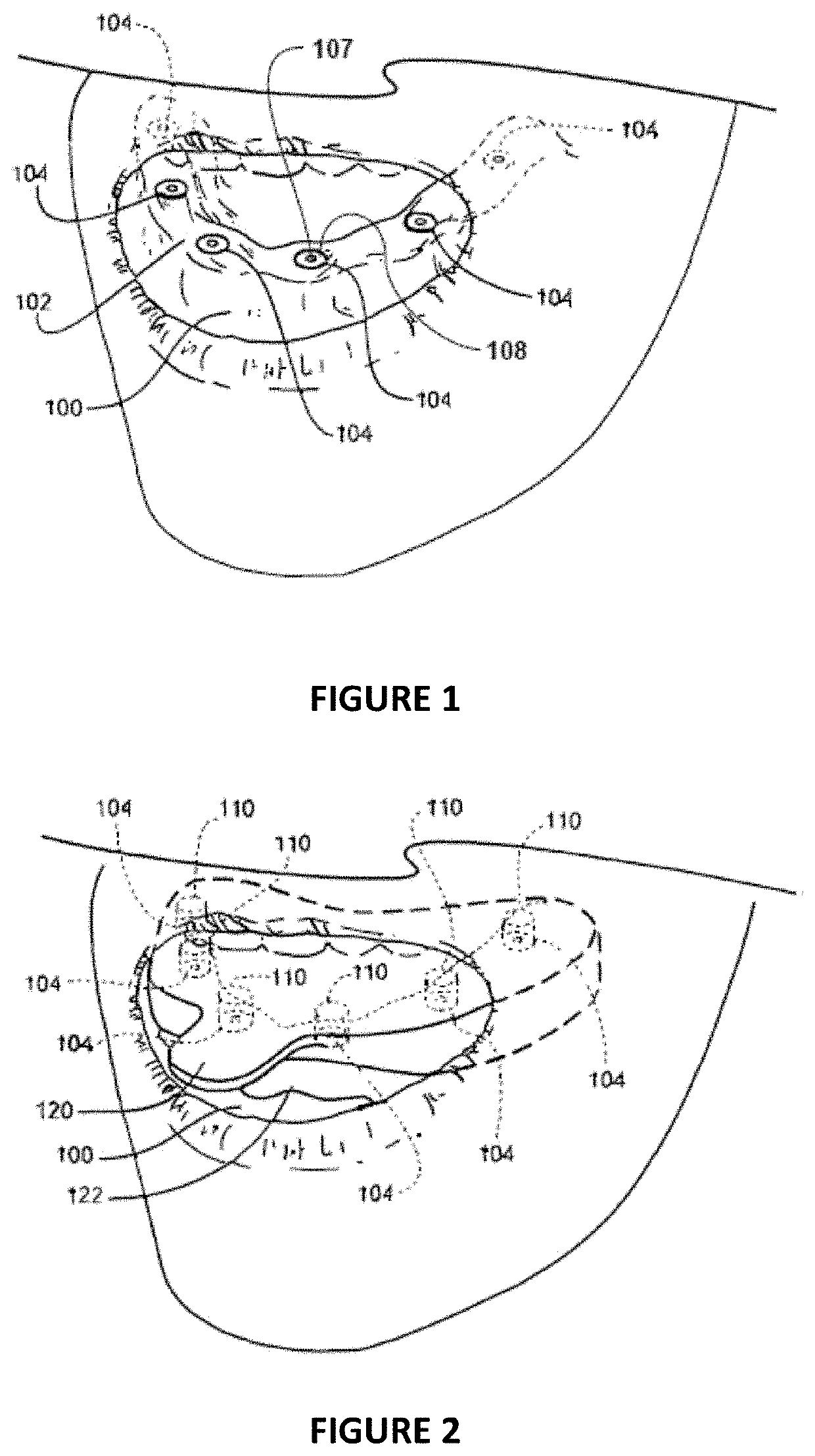
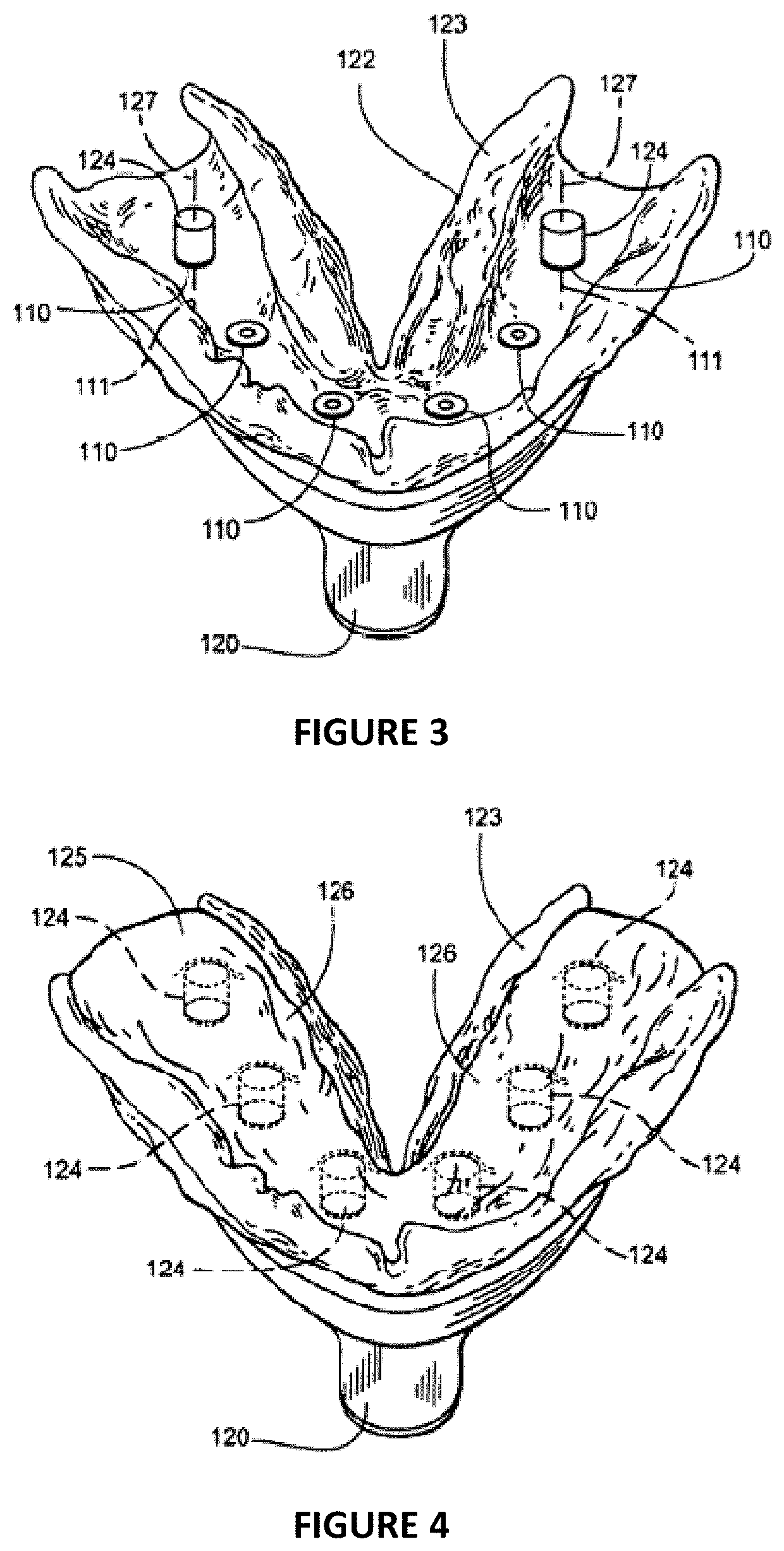
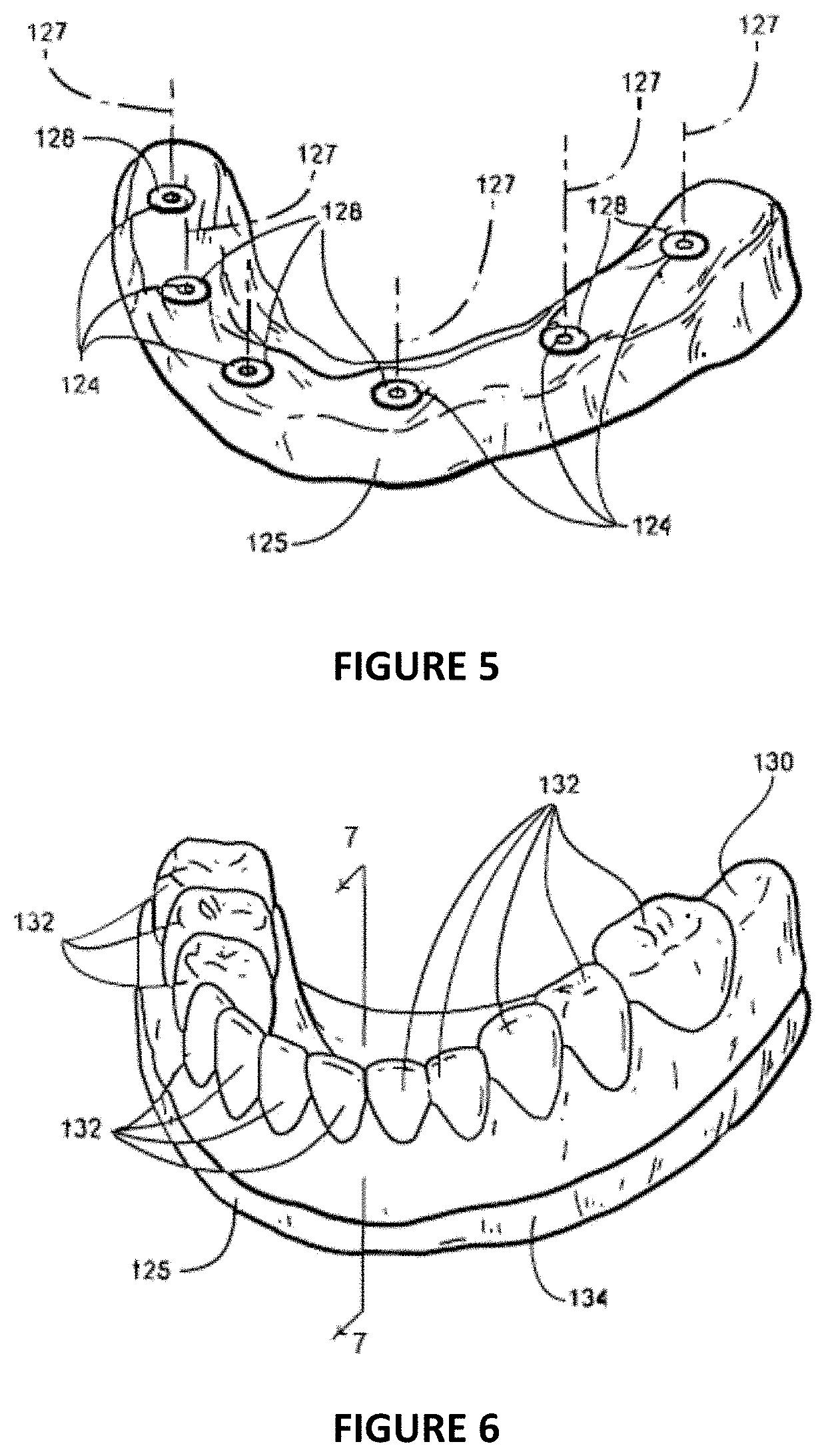
This patent describes a dental prosthesis consisting of a dental implant framework and a series of crowns that are designed to mate with the implants and abutments in a patient's mouth. The crowns are a part of an assembly consisting of a crown and a support post, which are easily editable to meet any clinical or aesthetic demands of the patient. Bridging structures are used in connecting the support posts and the fittings that will mate with the implants and abutments. The combination of bridging structures, support posts, and fittings will provide the completed design of the dental implant framework. The dimensions of the crown and support post assemblies are known, which allows for simultaneous design and manufacture of the dental implant framework and crowns. A CAD library of crowns and support posts is also disclosed, which provides a rapid design process for the fabrication of a dental implant framework and crowns.

Problems solved by technology

This process has several challenges, namely that it only utilizes a portion of the spatial dimensions of a patient's mouth, it requires technicians to purchase copings and screws to generate, and is extremely time intensive.
The technician is somewhat limited in designing the individual crown framework as he / she only has the facial boundary of the diagnostic wax up to utilize as a guide.
The technician will be extremely limited in being able to visualize the correct position of the framework in the occlusal and lingual dimensions for the case.
There will also be limits in determining the position of the margins where each individual crown will mate with the framework.
The casting technology traditionally used in fabricating the framework is fraught with errors and usually results in the framework having to be cut and soldered in order to properly mate with the implants in the patient's mouth.
This cutting and soldering process results in additional visits for the patient and weakens the overall strength and integrity of the framework.
The copymill process provides improvements to the fit of the individual crown framework to the implants in the patient's mouth, but there are limits associated with tool access in cutting many of the finer geometries the dental technician incorporated in the design of the framework.
This issue of excess material is especially problematic in dealing with the margins where the individual crowns will mate to the framework.
Refining the milled framework is once again an extremely time intensive task requiring a highly trained technician.

Method used


Image

  • Dental Implant Framework
  • Dental Implant Framework
  • Dental Implant Framework

Examples


first embodiment

[0092]In the invented process, the dentist and / or technician will create a stone cast 125 and diagnostic wax-up 130 as previously discussed. It is from these elements, where the invented process will allow for the simultaneous design and fabrication of the crowns and framework. First a digital scan of the stone cast 125 utilizing the alignment posts 156 attached to the analogs 124 as detailed in application Ser. No. 11 / 875,826, is conducted. This process will determine the exact location of the critical mating geometries and their correlation relative to one another as well as relative to the soft tissue contours captured in the stone cast. As demonstrated in FIG. 12, in step 214 of the process, the dentist sends the stone cast 125 and diagnostic wax up 130 to the laboratory. In step 216, the laboratory inserts alignment posts 156 into the analogs 124 embedded in the stone cast 125. These alignment posts 156 are configured to engage the mating surfaces of analogs 124 and hold the al...

third embodiment

[0130]In a third embodiment, the dentist or technician can utilize a CT scan or series of CT scans for the basis of determining the appropriate position of the crown / PTF Assemblies 316 and the digitally parameterized fittings 152″. The dentist or technician can use the CT scan data for determining or planning the position of the implant locations and ultimately the position of the digitally parameterized fittings 152″. The use of a radiographic stent demonstrating the ideal tooth position for the restoration can also be included in this process and provide the dentist and technician with an ability to align the Crown / PTF Assemblies 316 relative to the contours of the radiographic stent or relative to the position of the opposing arch. The dentist or technician could also utilize a CT scan of the patient's previous existing dentition, which could be aligned utilizing anatomical markers, in order to determine the ideal position of the Crown / PTF Assemblies 316.

[0131]These alternate emb...


PUM


Abstract

An improved method of a dental framework design and manufacturing, incorporating a dental framework design volume to eliminate framework or denture teeth modification post framework manufacturing.

Description

CROSS-REFERENCE TO RELATED APPLICATIONS[0001]66,821,238May, 2013Schuler, et al.14,272,566May, 2014Schulter, et alSTATEMENT REGARDING FEDERALLY SPONSORED RESEARCH OR DEVELOPMENT[0002]Not ApplicableREFERENCE TO SEQUENCE LISTING, A TABLE, OR A COMPUTER PROGRAM LISTING COMPACT DISC[0003]Not ApplicableDESCRIPTIONField of the Invention[0004]Dental prosthetics having individual crowns placed on top of a framework is becoming more popular due to improved aesthetics of individual crowns and the ability to replace and repair an individual crown when chipped, broken, or otherwise damaged as opposed to having to replace or repair the entire prosthesis as a unit. However, the process for the development of the framework has several challenges, namely that it only utilizes a portion of the spatial dimensions of a patient's mouth, it requires technicians to purchase copings and screws to generate, and is extremely time intensive. A need exists for a method in which one can easily and readily ident...

Claims


Application Information

Patent Timeline
IPC IPC(8): A61C13/01A61C13/00
CPCA61C13/01A61C13/34A61C13/0004A61C13/26A61C8/0048A61C13/102
Inventor SCHULTER, DREWSCHULTER, CARLFRAYSUR, KYLENEWMAN, DARYLHAMADEH, BELAL
Owner CAGENIX
Learn More