Lighting equipment

a technology of lighting equipment and light source, which is applied in the direction of electric lighting with batteries, semiconductor devices for light sources, lighting and heating apparatus, etc., can solve the problems of difficult factitious control of the size of the gap, damage to the eyes, and dizziness and discomfort of a person, etc., and achieves convenient use, simple operation, and flexible control

Active Publication Date: 2020-06-04
HANGZHOU GREAT STAR IND CO LTD +1
View PDF11 Cites 8 Cited by
  • Summary
  • Abstract
  • Description
  • Claims
  • Application Information

AI Technical Summary

Benefits of technology

[0032]The present invention has the advantages that the lighting equipment provided herein is provided with both the LED light source and the COB light source, so the user can flexibly control the two groups of light sources simply by using a single hand, which is simple in operation and convenient in use. The present invention has good circuit stability and low fault rate. The present invent

Problems solved by technology

Traditional lighting equipment, such as a flashlight and a searchlight, usually use LED lights as the light source inside their lamp heads, can only perform simple illumination, and are prone to cause dizziness and discomfort to a person after looking at the LED light sources for a long period, or even damage the eyes.
When these two ways are adopted to adjust the light beam of the flashlight, the user often needs to use two hands to operate, which is inconvenient

Method used


Image

  • Lighting equipment
  • Lighting equipment
  • Lighting equipment

Examples


first embodiment

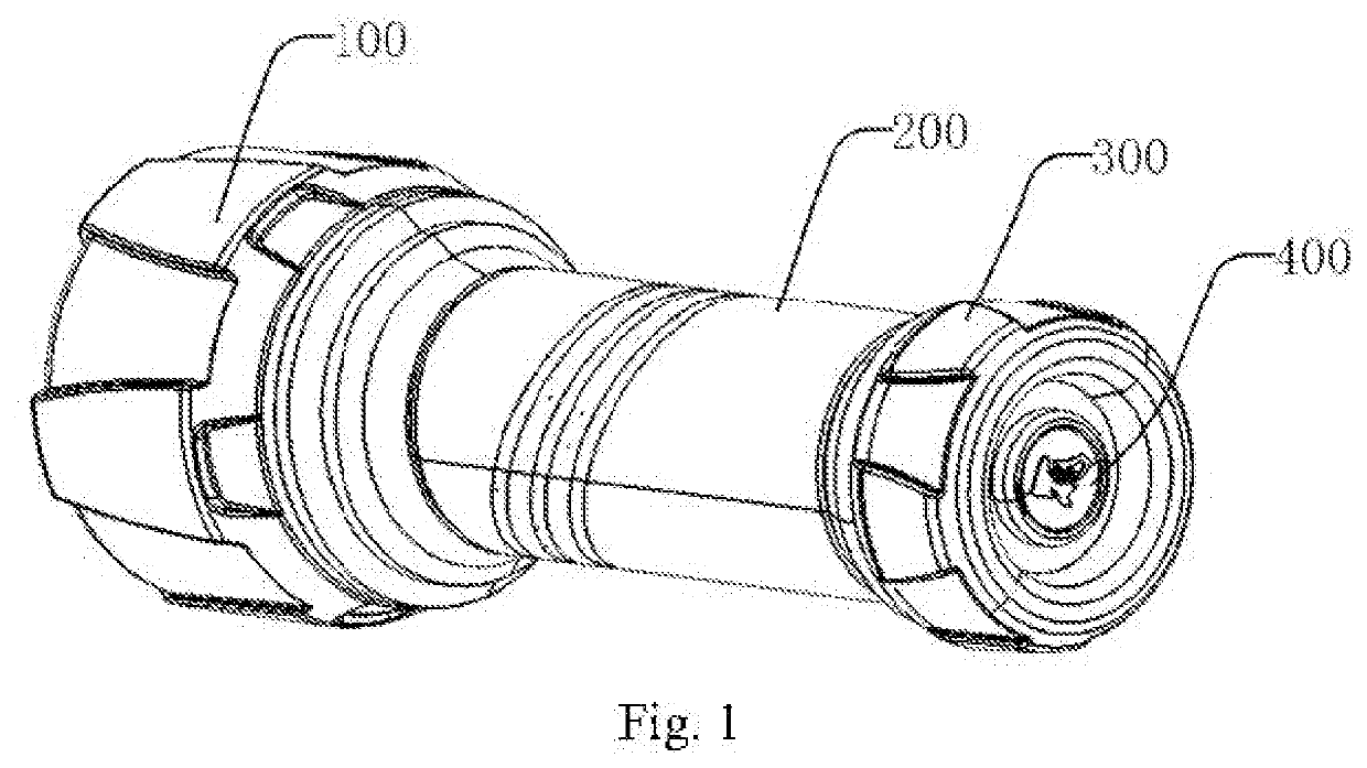
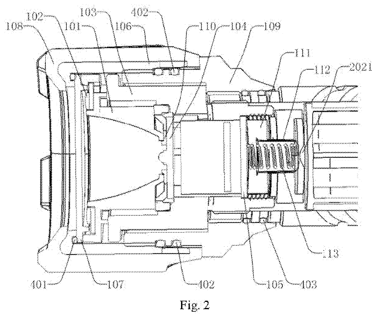
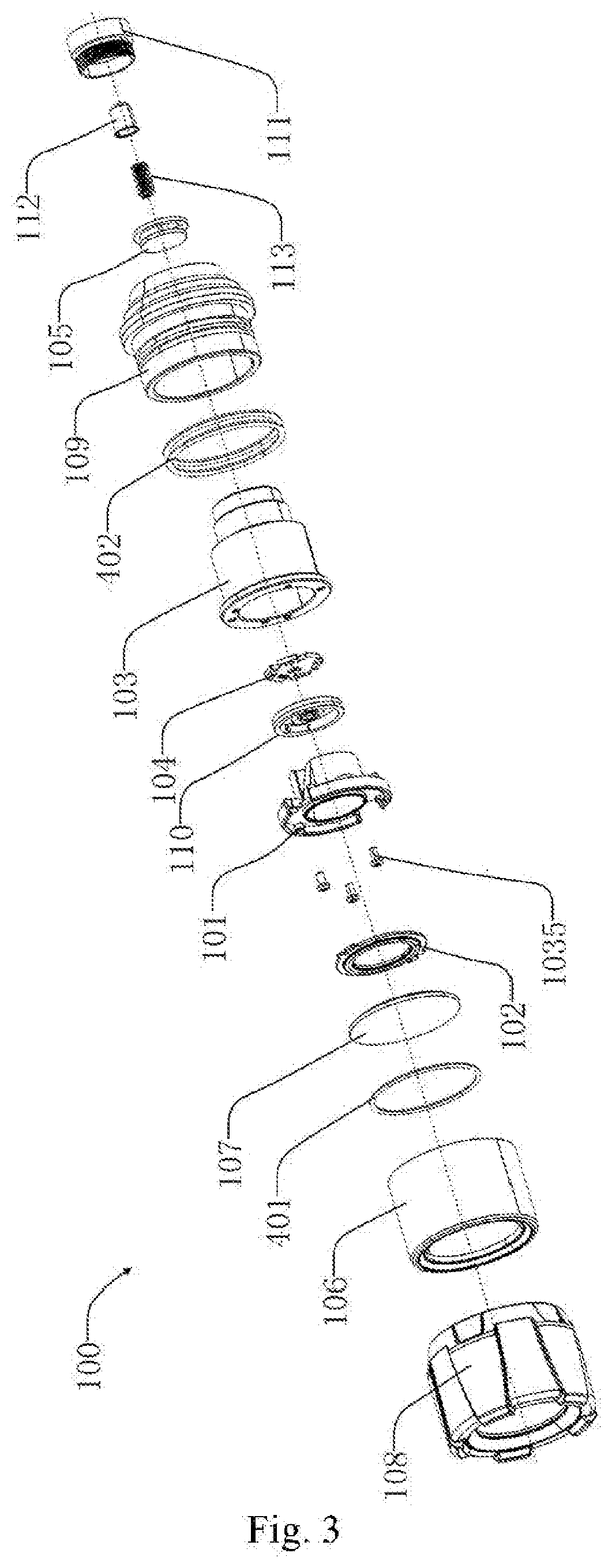
[0080]As shown in FIGS. 2-3, the lamp head portion 100 includes a reflective member 101, a COB lamp plate 102, a lamp bead base 103, an LED lamp plate 104, a light source circuit board 105, a lamp head inner casing 106, a light transmitting member 107, a lamp head outer casing 108 and a lamp head base 109.

[0081]As shown in FIGS. 4-5, the reflective member 101 includes a reflective member main plate 1011, a tapered reflective surface 1012 and at least one reflective member through hole 1013, which are integrated. The surface at one side of the reflective member main plate 1011 is provided with a protruding tapered reflective surface 1012 in the middle. The tapered reflective surface 1012 includes a large open end 10121 and a small open end 10122, the large open end 10121 arranged in the middle of the reflective plate main plate 1011. The reflective member through hole 1013 penetrates through the reflective member main plate 1011; various kinds of wires for electrical connection pass ...

second embodiment

[0116]As shown in FIGS. 23-24, most of the technical solutions in the present embodiment are the same as the first embodiment. The same technical solutions are not repeated herein, and their distinctive technical features refer to the following for details.

[0117]As shown in FIGS. 25-26, the reflective member 101 does not include a heat fin 1017, but only includes a heat sink 1018. The heat sink 1018 is provided thereon with a heat sink notch 10181. Various kinds of wires may pass through the heat sink notch 10181. The structural features of other members of the reflective member 101 are consistent with those in the first embodiment, without repeated description herein.

[0118]As shown in FIGS. 27-28, the lamp bead base 103 does not include a first hollow cavity of the lamp bead base 1033, but includes a lamp bead mounting slot 1035; the lamp bead mounting slot 1035 and the second hollow cavity of the lamp bead base 1034 are arranged at the two sides of the lamp bead base partition pla...

third embodiment

[0129]As shown in FIG. 33, most of the technical solutions in the present embodiment are the same as the first embodiment or the second embodiment. Their distinctive technical features refer to the following for details.

[0130]The lamp head portion 100 includes a light source bracket 117, for mounting the short distance light source and the long distance light source which are located on the same plane. The short distance light source is preferably one COB lamp plate, and the long distance light source is preferably one LED lamp plate. That is, the COB lamp plate 102 and the LED lamp plate 104 are located on the same plane.

[0131]The lamp head portion 100 further includes a tapered lens 118 and a lens bracket 119.

[0132]The two ends of the tapered lens 118 are a large lens face 1181 and a small lens face 1182 respectively, the small lens face 1182 provided with a lens recess 1183 in the middle; the lens bracket 119 is used for mounting the tapered lens 118, the shape of the lens bracke...


PUM


Abstract

The present invention provides a lighting equipment, which successively includes a lamp head portion, a connecting portion and a tail portion; the lighting equipment further includes a short distance light source, a long distance light source, a power supply and a control switch. The short distance light source and the long distance light source are arranged inside the lamp head portion, and the light emitting direction of the short distance light source is consistent with that of the long distance light source. The power supply is provided inside the connecting portion, a positive electrode and a negative electrode of which are electrically connected to two ends of the short distance light source and two ends of the long distance light source respectively. The control switch is used for controlling a light and shade state of the short distance light source and the long distance light source.

Description

FIELD OF THE INVENTION[0001]The present invention relates to the field of lighting equipment, and in particular to a lighting equipment.DESCRIPTION OF THE PRIOR ART[0002]Traditional lighting equipment, such as a flashlight and a searchlight, usually use LED lights as the light source inside their lamp heads, can only perform simple illumination, and are prone to cause dizziness and discomfort to a person after looking at the LED light sources for a long period, or even damage the eyes.[0003]Generally, prior lighting equipments are only provided with an LED light source, the long and short distance light adjustment of which is usually implemented by adjusting the distance between a lamp bead and a reflective surface to achieve the convergence and divergence effects of the light source. The most common way to adjust the distance between the lamp bead and an outermost lampshade is by drawing or rotating a head portion of the flashlight, thereby adjusting the convergence and divergence ...

Claims


Application Information

Patent Timeline
IPC IPC(8): F21V7/00F21V23/04F21L4/08F21V5/00F21V29/505
CPCF21V5/005F21L4/085F21V23/0421F21Y2115/10F21V7/0075F21V29/505F21L4/025F21L4/027F21Y2103/33
Inventor LI, YUEMING
Owner HANGZHOU GREAT STAR IND CO LTD
Why Eureka
Try Eureka