
Penetrator Projectile for Explosive Device Neutralization

a technology of explosive device and projectile, which is applied in the direction of projectiles, ammunition projectiles, weapons, etc., can solve the problems of more rapid fracture and high stress of components, and achieve the effects of low shock impulse production, low stress, and minimal fragmentation and spallation

Active Publication Date: 2020-06-04
THE UNITED STATES OF AMERICA AS REPRESENTED BY THE FEDERAL BUREAU OF INVESTIGATION DEPT OF JUSTICE
View PDF0 Cites 8 Cited by
  • Summary
  • Abstract
  • Description
  • Claims
  • Application Information

AI Technical Summary

Benefits of technology

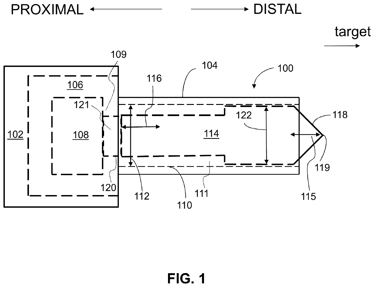
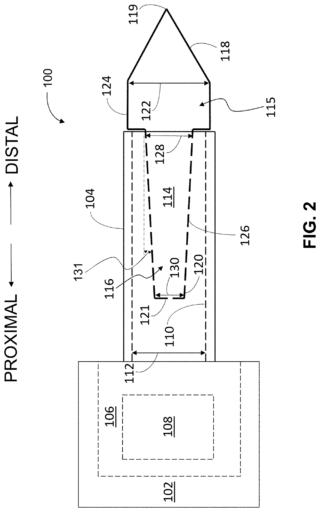
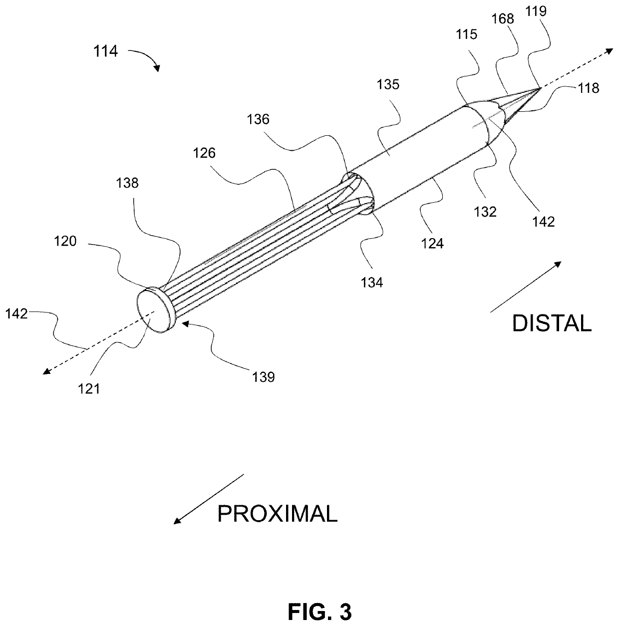
The patent text is describing a new type of explotive device disrupter called Short Pulse Intense Kinetic Energy (SPIKE) penetrators. These penetrators are designed to have high accuracy, minimal fragmentation and spallation, and low shock impulse production upon target interaction. This is important because it allows for safe and effective disruption of explosive devices. The design of these penetrators is achieved by specially selecting and configuring the various parts to ensure ballistic stability by positioning the center of pressure (CP) at a different location than the center of gravity (CG). This separation distance between the CP and CG should be at least 0.5 inches, preferably between 0.5 and 2 inches, to provide a stable free-flight characteristic. The SPIKE penetrators can be used for applications related to explosive device disruption.

Problems solved by technology

The transition zone(s) between two or more different tip profile regions can beneficially result in a higher stress on impact with components, thereby resulting in a more rapid fracture of the component.

Method used


Image

  • Penetrator Projectile for Explosive Device Neutralization
  • Penetrator Projectile for Explosive Device Neutralization
  • Penetrator Projectile for Explosive Device Neutralization

Examples


Embodiment Construction

[0052]In general the terms and phrases used herein have their art-recognized meaning, which can be found by reference to standard texts, journal references and contexts known to those skilled in the art. Referring to the drawings, like numerals indicate like elements and the same number appearing in more than one drawing refers to the same element. The following definitions are provided to clarify their specific use in the context of the invention.

[0053]The term “chamber” refers to the portion of the barrel of the EOD disrupter in which an explosive cartridge is positioned.

[0054]The term “breech” refers to the enclosure at the rear of the disrupter that contains the action. In some cases, the chamber can be part of the breech. In some cases the terms chamber and breech are used interchangeably.

[0055]The term “forcing cone” refers to the region of the bore that is a tapered transitional zone that reduces the diameter from the chamber diameter to the smaller bore diameter. One reason ...


PUM


Abstract

Provided herein are penetrator projectiles for use with explosive ordnance disposal disrupters, and related methods of making and using. The penetrator projectile has a tip, neck, shaft and base, wherein the geometry and composition of the different elements are selected to ensure the projectile is ballistically stable after firing to provide improved free-flight characteristics and corresponding explosive ordnance disruption.

Description

STATEMENT OF GOVERNMENT INTEREST[0001]The invention described herein was invented by an employee of the United States Government and thus, may be manufactured and used by or for the U.S. Government for governmental purposes without the payment of royalties.BACKGROUND OF INVENTION[0002]In the art of hazardous devices access and disablement, including explosive ordnance disposal, a common tool, particularly for neutralizing improvised explosive devices (IEDs), is a disrupter or dearmer, also referred herein as a propellant driven disrupter. As described in U.S. patent application Ser. No. 15 / 731,874, filed Aug. 18, 2017 and titled “Highly Efficient Energy Transfer Fluids,” the disrupters may fire a liquid projectile. Certain disrupter adaptations can be utilized to further increase the capabilities of the liquid projectile, including U.S. patent application Ser. No. 15 / 896,760 filed Feb. 14, 2018 and titled “Reverse Velocity Jet Tamper Disrupter Enhancer”. Although such liquid project...

Claims


Application Information

Patent Timeline
IPC IPC(8): F42B12/08F42D5/04
CPCF42D5/04F42B12/08F42B12/06
Inventor VABNICK, IAN B.
Owner THE UNITED STATES OF AMERICA AS REPRESENTED BY THE FEDERAL BUREAU OF INVESTIGATION DEPT OF JUSTICE
Learn More