
System for treating wash waste liquid, adapted for application in a continuous tunnel washing machine in the field of preclinical pharmaceutical research

a technology for washing machines and waste liquid, applied in the field of system for treating wash waste liquid, can solve the problems of blocking the filter, ineffective washing process, and the inability of self-cleaning systems to exploit idle times between washing cycles

Active Publication Date: 2020-06-11
IWT SRL
View PDF99 Cites 2 Cited by
  • Summary
  • Abstract
  • Description
  • Claims
  • Application Information

AI Technical Summary

Benefits of technology

The present invention proposes a system for treating wash waste liquid in a continuous Tunnel washing machine for Preclinical Pharmaceutical Research. The system includes an in-line filtering system that can clean itself automatically with a water consumption compatible with the standard consumption of the machine. It also includes a mechanism for separating the solid part from the rest of the wash bath as the latter is conveyed towards the drain. The system improves the treatment of wash waste liquid and overcomes the drawbacks of prior-art systems.

Problems solved by technology

For this reason, such machines employ filtering systems adapted to protect the wash nozzles against the risk of clogging, which would result in an ineffective wash process.
In continuous washing machines, restoration of static systems may only occur after stopping the machine and, unlike batch-type machines, self-cleaning systems cannot exploit the idle times between washing cycles.
Where high productivity is required or the amount of dirt is considerable, however, it is necessary to employ self-cleaning systems, with the resulting complexity.
1) With an in-line filter and counter-pressure cleaning, the self-cleaning process must be carried out at frequent intervals: if the filter cartridge becomes overfilled between one counter-cleaning cycle and the next (even if the filter still has sufficient filtering capacity during the process), it will become impossible to restore the filter by counter-pressure. Over time, this will lead to complete obstruction of the filter, resulting in the need for manual cleaning operations, which may be rather complex. Moreover, counter-cleaning requires a considerable amount of wash bath, which is expelled during the process, so that much time is necessary for restoring the bath volume, temperature and detergent concentration. On a continuous machine, this task could only be carried out when the machine is stopped, when it might already prove ineffective.
Control systems may be implemented, but it is clear that, due to the continuous nature of the machine, frequent stops may be unacceptable.
Moreover, since in this case the filter can only be installed on the delivery side of the centrifugal pump for bath circulation, where there is sufficient pressure, all residues will go through the impeller, and in a continuous process this may lead to blockage of the impeller itself.
2) With flat filters and filter wipers, the essential problem is the complexity of the system.
Furthermore, the filter wiper, which is typically a brush, crushes dirt residues on the filter until they inevitably go through the filtering wire mesh.
The filtering area may need to be quite large, thus affecting design choices as to the tub geometry.
In addition, it is necessary to provide a suitable seal between the filtering wire mesh and its housing in the tub: this is not always an easy task, and tightness is not always ensured.
In the former case, the result of the operation depends on the operator's sensitivity, whereas in the latter case the systems are complex, since they include additional robots or axes and are not very flexible (they can process only one or only a few types of cages).2) Water scraper: in this case, a throwaway high-pressure water jet is used for the removal operation.
It is clear that in this case the problem is the huge water consumption necessary for the execution of this step.
When water-based solutions are employed, at any rate, the solid dirt part removed will dissolve into the wash bath, and sooner or later will be drained along with it: it is apparent that separating this part of dirt from the remaining waste is a problem that cannot be easily solved.
It is possible, in fact, that the rules and laws of the country where the machine is to be installed do not allow for free dumping of particulate, and the animal breeding department is likely to lack a centralized treatment system.
In this case as well, solutions are available on the market which employ scrolls and brushes, the construction of which is however very complex.
Another known problem relates to the height of the loading plane of continuous washing machines, which must be within the limits set forth by the law in order to comply with operator ergonomics criteria.
In the continuous washing machines currently known in the art, therefore, the bath level is very low with respect to the inlet port of the centrifugal circulation pump, with limited priming capabilities especially when working in the presence of detergents and high bath temperatures.
In order to prevent the centrifugal pump from suffering possible cavitation phenomena, complex and costly solutions are resorted to, such as, for example, specially shaped intake channels, which will nevertheless reduce the performance of the machine.

Method used


Image

  • System for treating wash waste liquid, adapted for application in a continuous tunnel washing machine in the field of preclinical pharmaceutical research
  • System for treating wash waste liquid, adapted for application in a continuous tunnel washing machine in the field of preclinical pharmaceutical research
  • System for treating wash waste liquid, adapted for application in a continuous tunnel washing machine in the field of preclinical pharmaceutical research

Examples


Embodiment Construction

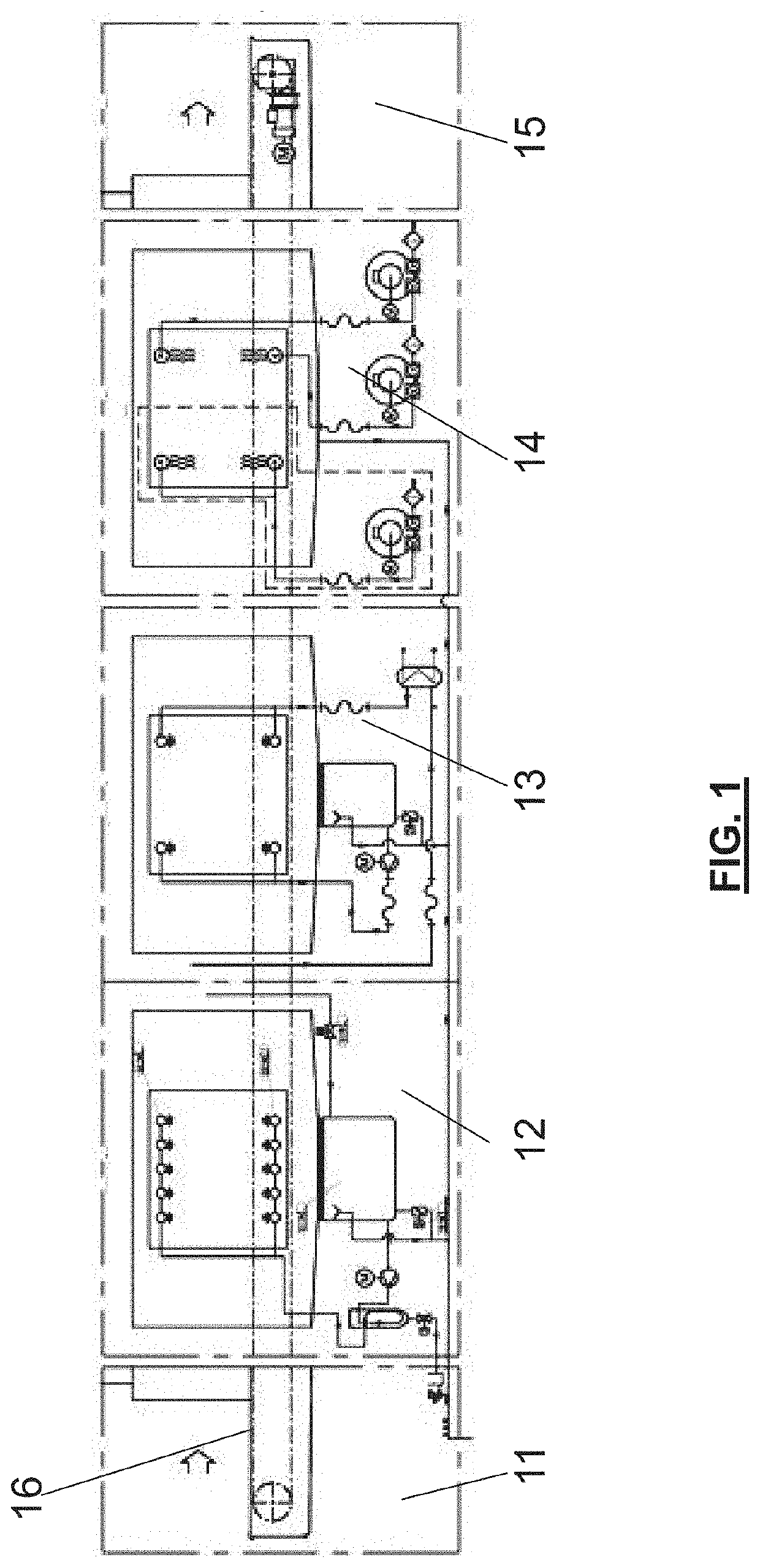
[0049]The tunnel-type system (FIG. 1) is made up of a series of in-line modules. Typically, the most common configuration includes a load module 11 of a substantially known type, followed by a wash module 12, to which the present invention applies, a rinse module 13 of a substantially known type, a blow module 14 of a substantially known type, and an unload module 15 of a substantially known type.

[0050]The cages / components to be washed are loaded onto the load module 11, and then a belt 16, which is common to all modules, carries them towards the wash module 12 and the remaining modules 13, 14 and 15 that follow.

[0051]Removal of the dirt (including solid dirt) occurs in the wash module 12, where the dirt is collected and processed by the machine.

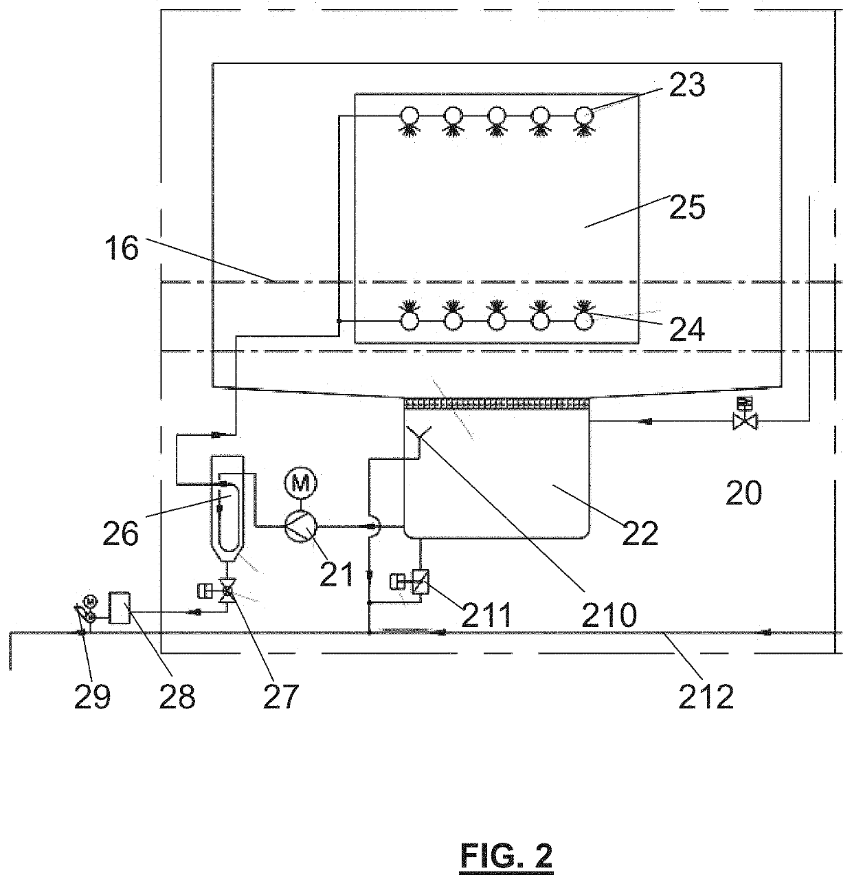
[0052]In the wash module (FIG. 2), a wash pump 21, by taking in washing solution (water and detergent at a given temperature) from a tub 22, generates a wash flow towards the nozzles 23, 24 in the wash chamber 25. The wash flow hits in all d...


PUM

PropertyMeasurementUnit
shapeaaaaaaaaaa
gravityaaaaaaaaaa
temperatureaaaaaaaaaa

Abstract

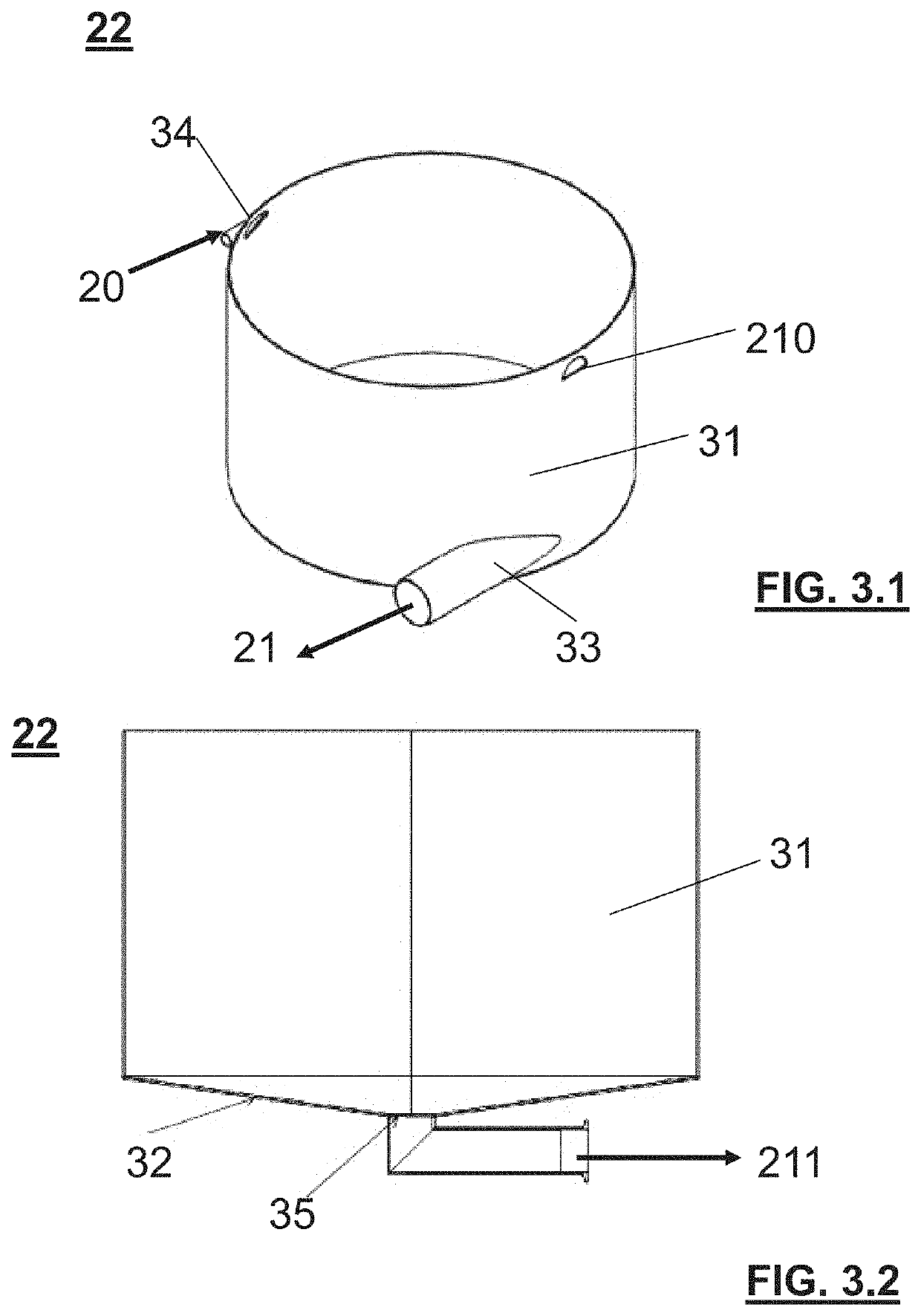
A system for treating wash waste liquid is described, configured for coupling to a wash module of a continuous Tunnel washing machine for the field of Preclinical Pharmaceutical Research, said wash module (12) comprising a wash chamber (25), characterized in that it comprises:a wash tub (22) with a side wall (31) substantially cylindrical in shape, with a tangential liquid suction outlet (33) and a substantially conical bottom, with a wash waste drain point (35) at the vertex of the cone, said tangential suction being adapted to generate a rotational motion of the liquid in said tub, said tub being positioned under said wash chamber (25), so as to receive said wash liquid by gravity;a centrifugal wash pump (21) with an open impeller, adapted to take in liquid from said tangential liquid suction outlet (33);an in-line filter (26) with an internal filter cartridge of the “wedge-wire” type, adapted to filter the liquid coming from said centrifugal pump (21) and deliver it back, filtered, into said wash chamber (25), and comprising a flush valve (27) for discharging the filtering waste.

Description

FIELD OF APPLICATION OF THE INVENTION[0001]The present invention relates to a system for treating wash waste liquid, configured for use in a continuous Tunnel washing machine for the field of Preclinical Pharmaceutical Research, particularly for washing breeding cages for animals to be used for research purposes, as well as various other components used in preclinical pharmaceutical research centres.STATE OF THE ART[0002]It is known that in the field of preclinical pharmaceutical research it is necessary to use wash systems that allow cleaning the breeding cages for animals used for research purposes and various other components used during the breeding process.[0003]The wash procedures known in the art, the purpose of which is to remove contaminants, food residues and animal excrements, as well as bedding and any enrichment placed on the cage bottom to make the animals more comfortable, are of three types:[0004]Manual: by executing a special procedure using water jets and / or deterg...

Claims


Application Information

Patent Timeline
Patent Type & Authority Applications(United States)
IPC IPC(8): B08B3/14B01D39/20B01D35/02B01D29/90B01D29/92A46B9/02A46B13/00B01D29/64B08B3/04B01D29/35B01D29/66A01K1/03A01K1/01
CPCA46B13/001A46B9/026A01K1/031B01D35/02B01D29/90A01K1/01B08B3/041B01D29/668B08B3/14B01D39/2027B01D29/6415B01D29/92B01D29/356B01D2201/325B08B3/10
Inventor BORGHI, MATTEOVITALI, MICHELE
Owner IWT SRL
Learn More