Motion transmission unit, drive train and hair cutting appliance

Active Publication Date: 2020-06-11
KONINKLJIJKE PHILIPS NV
View PDF0 Cites 2 Cited by
  • Summary
  • Abstract
  • Description
  • Claims
  • Application Information

AI Technical Summary

Benefits of technology

[0013]It is an object of the present disclosure to provide a motion transmission unit for a drive train of a hair cutting appliance that improves the overall cutting performance of the appliance and that preferably reduces internal stress and loads

Problems solved by technology

Hence, there are often design constraints that result in a certain angular offset between an input shaft and an output (normal of blade set movement plane) of the motion transmission unit.
It has been observed that, in terms of kinematics, connecting elements that are offset from one another by a considerable angle and, at the same time, arranged to convert a rotating input movement into

Method used


Image

  • Motion transmission unit, drive train and hair cutting appliance
  • Motion transmission unit, drive train and hair cutting appliance
  • Motion transmission unit, drive train and hair cutting appliance

Examples


Example

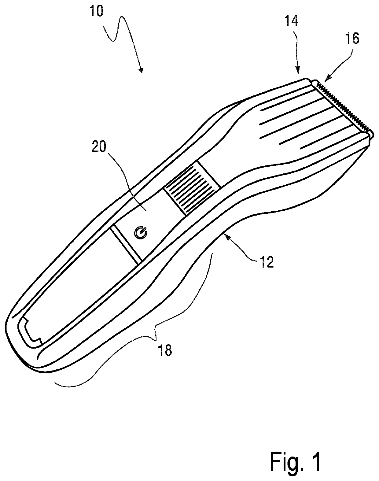
[0070]FIG. 1 shows a perspective view of a hair cutting appliance 10. The appliance 10 comprises a housing 12. Further, a cutting head 14 is provided that is disposed at or attached to the housing 12. At the cutting head 14, a blade set 16 is formed that involves a stationary blade and a cutter blade that are arranged to be moved with respect to one another to cut hair.

[0071]At a side of the housing 12 that is facing away from the cutting head 14, a handle portion 18 is provided. Further, indicated by reference numeral 20, controls are formed at the housing 12.

[0072]As can be seen from FIG. 1, the housing 12 has a generally elongated and somewhat curved shape. A user may grasp the appliance 10 in the handle portion 18 and guide the appliance 10 accordingly to cut hair with the blade set 16.

[0073]There are several design constraints and design goals for hair cutting appliances 10. For instance, a design of the housing 12 basically shall conform with industrial design goals, ergonomic...


PUM


Abstract

The present disclosure relates to a motion transmission unit (40) for a drive train (30) of a hair cutting appliance (10) and to a hair cutting appliance (10), the unit (40) comprising an input shaft (42) defining a longitudinal axis (44) and comprising an eccentric portion (68) that is arranged to revolve about the longitudinal axis (44) when the input shaft (42) is rotated, a motion converter (44) comprising a motion converter input interface (74) and a motion converter output interface (76), and a tilting lever (46) that is pivotably mounted and comprises a tilting lever input interface (80) and a tilting lever output interface (82) that engages a driving portion (86) of a blade set (16) of the appliance (10), wherein the motion converter (44) is arranged between the input shaft (42) and the tilting lever, wherein the eccentric portion (68) of the input shaft (42) engages the motion converter input interface (74), wherein the motion converter output interface (76) engages the tilting lever input interface (80), and wherein the motion converter input interface (74) and the motion converter output interface (76) are arranged at the same longitudinal level (140) with respect to the input shaft (42), wherein the motion converter output interface (76) comprises a cylindrical portion (102) defining a cylinder axis (104) that is basically parallel to a swivel axis (58) of the tilting lever (46), wherein the tilting lever output interface (82) is arranged as a cylindrical portion (126) defining a cylinder axis (130) that is basically parallel to a swivel axis (58) of the tilting lever (46), and wherein the cylinder axis (130) of the head portion (126) of the tilting lever (46) and the cylinder axis (104) of the cylindrical portion (102) of the motion converter (44) are basically parallel to the swivel axis (58).

Description

FIELD OF THE INVENTION[0001]The present disclosure relates to a motion transmission unit for a drive train of a hair cutting appliance and to a hair cutting appliance that is equipped with a respective motion transmission unit. More particularly, the present disclosure relates to motion transmission units that are capable of transmitting a driving motion for a blade set of a hair cutting appliance, wherein a certain inclination is present between a main orientation of an input shaft and (a normal of) a cutter blade (movable blade) of the blade set that is to be driven by the motion transmission unit. More particularly, but not to be understood in a limiting sense, the present disclosure relates to improvements in drive trains for hair cutting appliances having somewhat curved or banana-shaped casings, for ergonomic reasons, for product design reasons, and / or for reachability / visibility reasons, for instance.[0002]Furthermore, more generally, the present disclosure also relates to dr...

Claims


Application Information

Patent Timeline
IPC IPC(8): B26B19/28
CPCB26B19/3846B26B19/063B26B19/3853B26B19/28
Inventor PETRELLI, MARCUS CORNELISDE VRIES, ALWIN WILLIAM
Owner KONINKLJIJKE PHILIPS NV
Why Eureka
Try Eureka