Oxide coated cutting tool

Inactive Publication Date: 2004-03-30
SANDVIK INTELLECTUAL PROPERTY AB
View PDF15 Cites 50 Cited by
  • Summary
  • Abstract
  • Description
  • Claims
  • Application Information

AI Technical Summary

Benefits of technology

It is a further object of the invention to provide an alumina coated cutting tool insert with impr

Problems solved by technology

However such multilayer structures very often suffer from

Method used


Image

  • Oxide coated cutting tool
  • Oxide coated cutting tool
  • Oxide coated cutting tool

Examples


Example

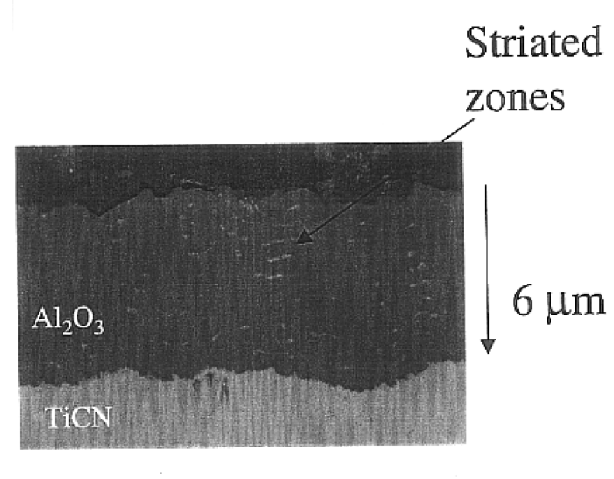
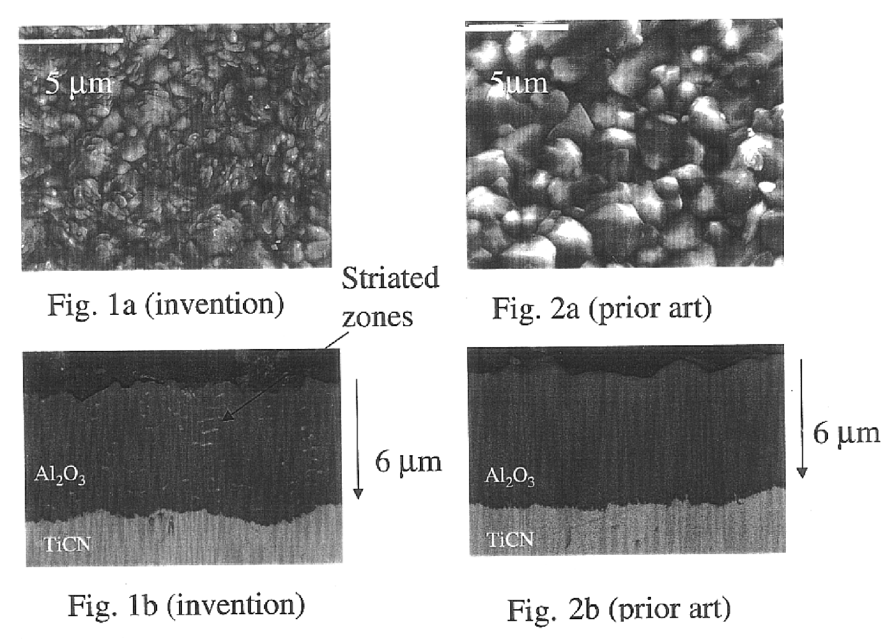
) Cemented carbide cutting inserts in style CNMG 120412-KM with the composition 6 weight-% Co and balance WC were coated with a 5 .mu.m thick layer of TI(C,N) using the MTCVD-technique with TiCl.sub.4, H.sub.2, N.sub.2 and CH.sub.3 CN as process gases. In subsequent process steps during the same coating cycle, a 0.5 .mu.m TiC.sub.x N.sub.y O.sub.z layer with an approximate composition corresponding to x=0.5, y=0.3 and z=0.2 was deposited followed by a 6 .mu.m thick layer of .alpha.-Al.sub.2 O.sub.3 deposited according to the invented coating process. Prior to the nucleation of the Al.sub.2 O.sub.3 the oxidation potential of the carrier gas H.sub.2 (only gas present in the reactor) i.e. the water vapor concentration, was explicitly set to a low level, i.e.--less than 5 ppm.

Then the first Al.sub.2 O.sub.3 layer step I was started up. The process conditions during the Al.sub.2 O.sub.3 deposition were as below:

The Al.sub.2 O.sub.3 layer was deposited by proceeding through step 1, 2 and ...


PUM

PropertyMeasurementUnit
Temperatureaaaaaaaaaa
Fractionaaaaaaaaaa
Fractionaaaaaaaaaa

Abstract

According to the present invention there is provided a body at least partially coated with one or more refractory layers of which at least one layer essentially consist of alpha-Al2O3. Said alpha-Al2O3 layer consists of essentially equiaxed grains with an average grain size of <1 mum and with a bimodal grain size distribution with coarser grains with an average grainsize in the interval 0.5-1 mum and finer grains with an average grainsize of <0.5 mum. The Al2O3 layer further contains striated zones containing titanium (>5 at %) but no nitrogen or carbon. This particular microstructure is obtained by temporarily stopping the gases needed for the growth of the Al2O3 layer and introducing TiCl4.

Description

The present invention relates to a coated cutting tool for chipforming machining. The coating includes at least one alumina (Al.sub.2 O.sub.3) layer characterized by fine, equiaxed grains.DESCRIPTION OF THE RELATED ARTIn the description of the background of the present invention that follows reference is made to certain structures and methods, however, such references should not necessarily be construed as an admission that these structures and methods qualify as prior art under the applicable statutory provisions. Applicants reserve the right to demonstrate that any of the referenced subject matter does not constitute prior art with regard to the present invention.Cemented carbide cutting tools can be coated with various types of Al.sub.2 O.sub.3 layers by using Chemical Vapour Deposition (CVD), e.g., pure .kappa.-Al.sub.2 O.sub.3, mixtures of .kappa.- and .alpha.-Al.sub.2 O.sub.3, coarse grained .alpha.-Al.sub.2 O.sub.3, and fine grained textured .alpha.-Al.sub.2 O.sub.3 have been...

Claims


Application Information

Patent Timeline
IPC IPC(8): C23C30/00C23C16/40C23C16/44B23B27/14B23C5/16B23P15/28C23C16/455
CPCC23C16/403C23C16/45523C23C30/005Y10T428/252Y10T407/26Y10T407/27Y10T117/10B23P15/28
Inventor LJUNGBERG, BJORNBUDZYNSKI, LARS-ANDERS
Owner SANDVIK INTELLECTUAL PROPERTY AB
Why Eureka
Try Eureka