
Coating materials for a cutting tool / an abrasion resistance tool

Inactive Publication Date: 2007-06-28
KORLOY
View PDF10 Cites 15 Cited by
  • Summary
  • Abstract
  • Description
  • Claims
  • Application Information

AI Technical Summary

Benefits of technology

[0014]Another object of the present invention is to provide a cutting tool deposited with an α-Al2O3 layer having improved cutting performance for steel, stainless steel, and cast iron, particularly general cast iron and nodular graphite cast iron.
[0021]The uppermost coating layer is preferably dry or wet blasted with Al2O3 powder to improve the surface roughness thereof.

Problems solved by technology

However, these patents disclose only the preferred growth of a specific crystal plane among the typical planes (012), (104), (110), (113), (024) and (116) of the α-Al2O3 layer, but do not disclose the relationship of the α-Al2O3 layer with the remaining crystal planes.

Method used


Image

  • Coating materials for a cutting tool / an abrasion resistance tool
  • Coating materials for a cutting tool / an abrasion resistance tool
  • Coating materials for a cutting tool / an abrasion resistance tool

Examples


example 1

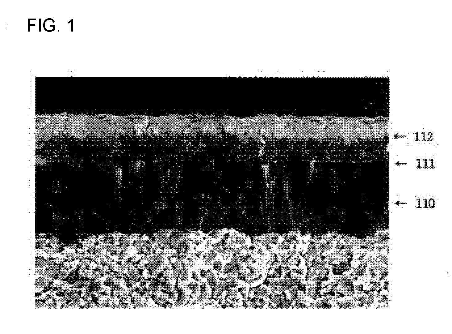
[0028](A) A TiCN layer having a thickness of 8 μm was deposited on cemented carbide for coated cutting tools corresponding to the ISO K05 grade by MT-CVD, and a 0.5 μm thick TiMewCxNyOz (Me=Zr, Hf, w+x+y+z=1, w, x, y, z≧0) layer according to the present invention was deposited thereon. Then, a 5 μm thick α-Al2O3 layer was deposited thereon.

[0029]As shown in Table 1 below, X-ray diffraction analysis for the coated material showed that the texture coefficient, TC(100), of the crystal plane (110) of the crystalline α-Al2O3 layer was 4.4, and the texture coefficient of the remaining crystal planes was smaller than 1.0.

TABLE 1Crystal planesTexture coefficient (TC)(012)0.93(104)0.05(110)4.44(113)0.09(024)0.46(116)0.03

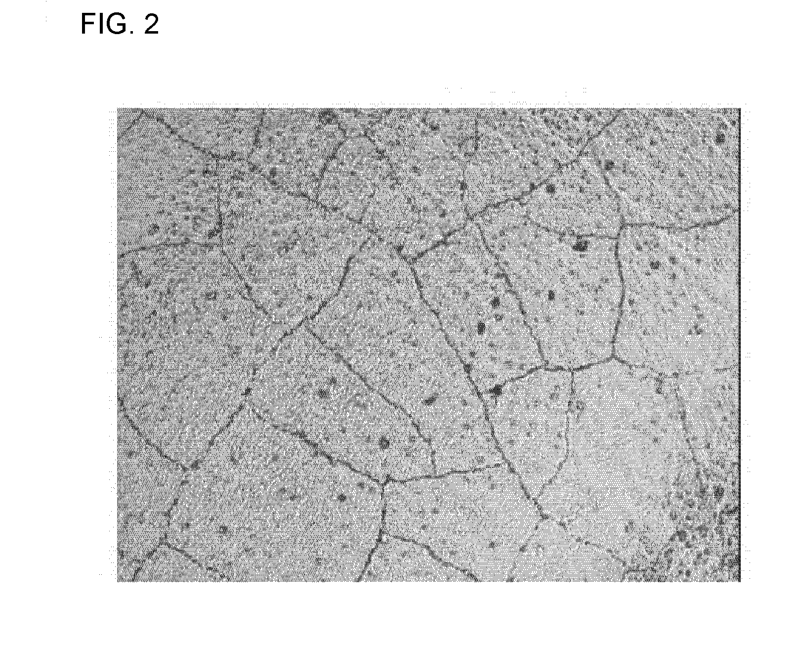
[0030]FIG. 2 shows the results of optical microscopy (360× magnification) for the surface of the layer fabricated in the above section (A). As shown in FIG. 2, thermal cracks were present even in the polycrystalline α-Al2O3 layer having a preferred crystal growth orientation ...

example 2

[0041](D) A TiCN layer having a thickness of 10 μm was deposited on cemented carbide corresponding to the ISO P10 grade through MT-CVD, and a 0.5 μm thick TiMewCxNyOz (Me=Zr, Hf, w+x+y+z=1, w, x, y, z≧0) layer according to the present invention was deposited thereon. Then, a 5 μm thick α-Al2O3 layer was deposited thereon. As shown in Table 5, X-ray diffraction analysis for the Al2O3 layer showed that the TC (110) of the (110) crystal plane of the polycrystalline Al2O3 layer was 4.96 and the TC of the remaining crystal planes was smaller than 1.0.

TABLE 5Crystal planesTexture coefficient (TC)(012)0.53(104)0.01(110)5.06(113)0.11(024)0.28(116)0.01

[0042]E) A 7 μm thick TiCN layer was deposited on cemented carbide corresponding to the ISO P10 grade by MT-CVD, and a 1.5 μm thick TiC layer and 3 μm thick K-Al2O3 layer were sequentially deposited thereon.

[0043]The coated cutting tools fabricated in the above sections D) and E) were dry or wet blasted with 200-mesh Al2O3 powder to improve the...


PUM

PropertyMeasurementUnit
Fractionaaaaaaaaaa
Fractionaaaaaaaaaa
Fractionaaaaaaaaaa

Abstract

Disclosed herein is an α-Al2O3 coating layer, which is applied on the surface of a cutting tool substrate made of cemented carbide, cermet or ceramic material. The α-Al2O3 layer is deposited on a TiMewCxNyOz (Me=Zr, Hf, w+x+y+z=1, w, x, y, z≧0) layer to a thickness of 2-1 5 μm through high-temperature chemical vapor deposition, such that the texture coefficient, TC(110), of the crystal plane (110) among the crystal planes (012), (104), (110), (113), (024) and (116) thereof is larger than 1.5, while the texture coefficient of the crystal planes (012), (104), (113), (024) and (116) is smaller than 1.0, said α-Al2O3 layer having thermal cracks. Thus, the α-Al2O3 layer has improved abrasion resistance and adhesion.

Description

CROSS REFERENCE[0001]Applicant claims foreign priority under Paris Convention and 35 U.S.C. §119 to the Korean Patent Application No. 10-2005-0128971, filed Dec. 23, 2005 with the Korean Intellectual Property Office.BACKGROUND OF THE INVENTION[0002]1. Technical Field[0003]The present invention relates to a coating layer for coated cemented carbides for use in cutting tools such as an indexable insert, and more particularly to a hard ceramic layer having improved abrasion resistance, which serves to improve abrasion resistance of cutting tools, as well as a cutting tool coated with said hard ceramic layer.[0004]2. Description of the Prior Art[0005]To increase the useful life cycle of cutting tools, hard ceramic coating layers by chemical vapor deposition process such as titanium carbide (hereinafter, referred to as TiC), titanium nitride (hereinafter, referred to as TiN), titanium carbon nitride (hereinafter, referred to as TiCN) and alumina (hereinafter, referred to as Al2O3) are ge...

Claims


Application Information

Patent Timeline
IPC IPC(8): B32B9/00B32B19/00
CPCC04B41/009C04B41/52C04B41/89C04B2111/0025C23C16/0272C23C16/403C23C30/005C04B41/4531C04B41/5061C04B41/5068C04B41/5031C04B35/00B23P15/28C22C27/04C23C16/32C23C16/36H01L21/205
Inventor PARK, GEUN-WOOHWANG, CHANG-GYUCHOI, YONG-HEE
Owner KORLOY
Learn More