Medical knife

Inactive Publication Date: 2005-03-31
KAI R&D CENT CO LTD
View PDF5 Cites 43 Cited by
  • Summary
  • Abstract
  • Description
  • Claims
  • Application Information

AI Technical Summary

Benefits of technology

[0005] Accordingly, it is an objective of the present invention to provide a medical knife

Problems solved by technology

This limits the cutting perf

Method used


Image

  • Medical knife
  • Medical knife
  • Medical knife

Examples


Example

[0034] A medical knife according to a first embodiment of the present invention will be described with reference to FIGS. 1(a) to 4(d).

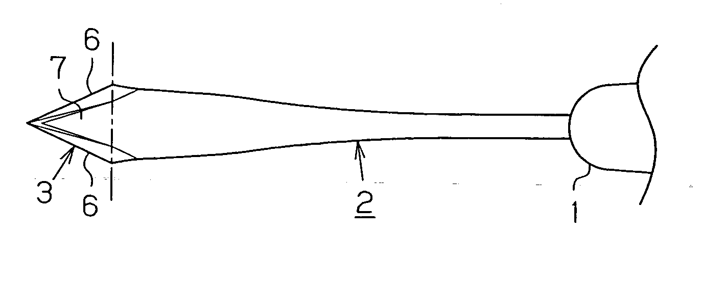
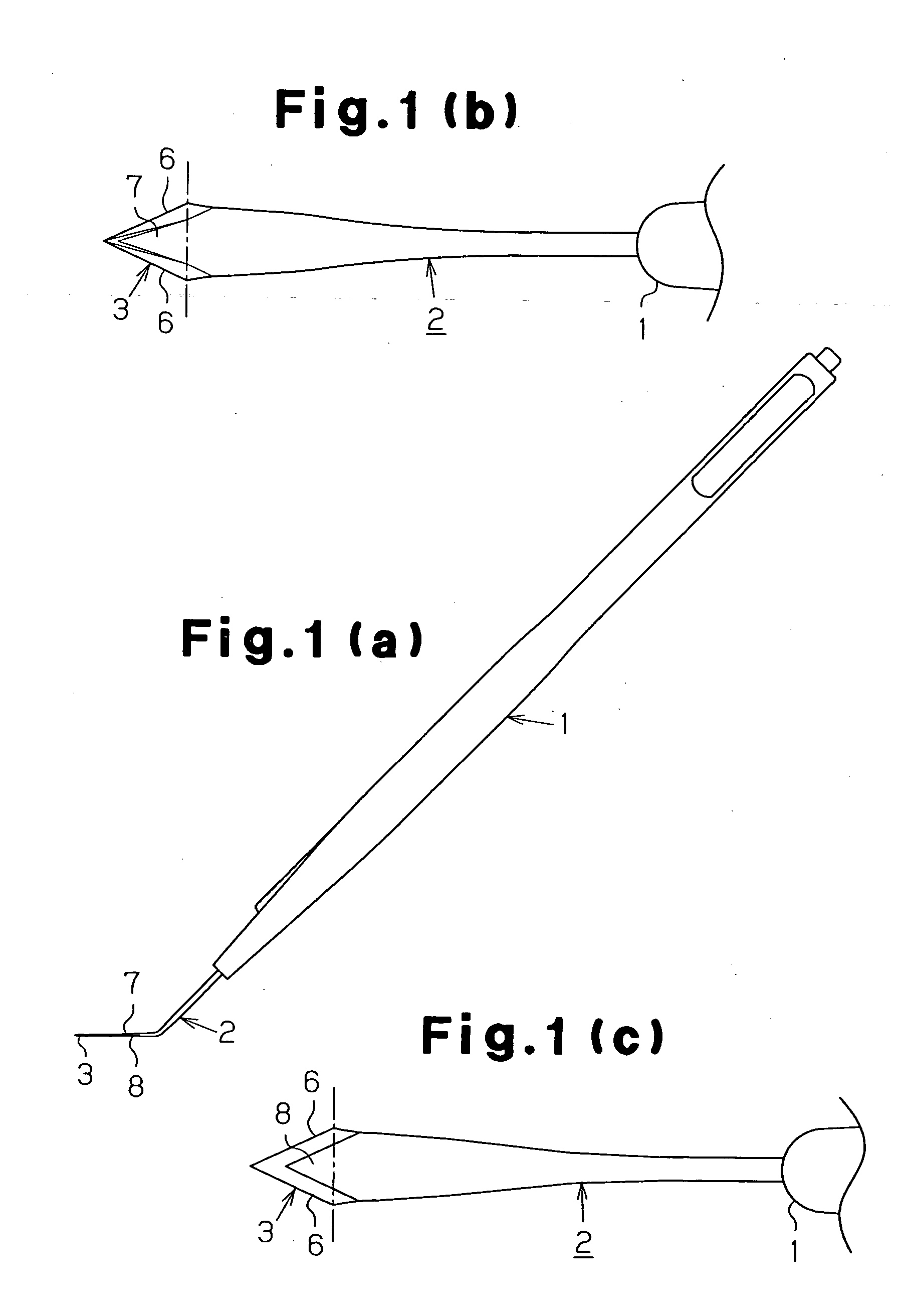
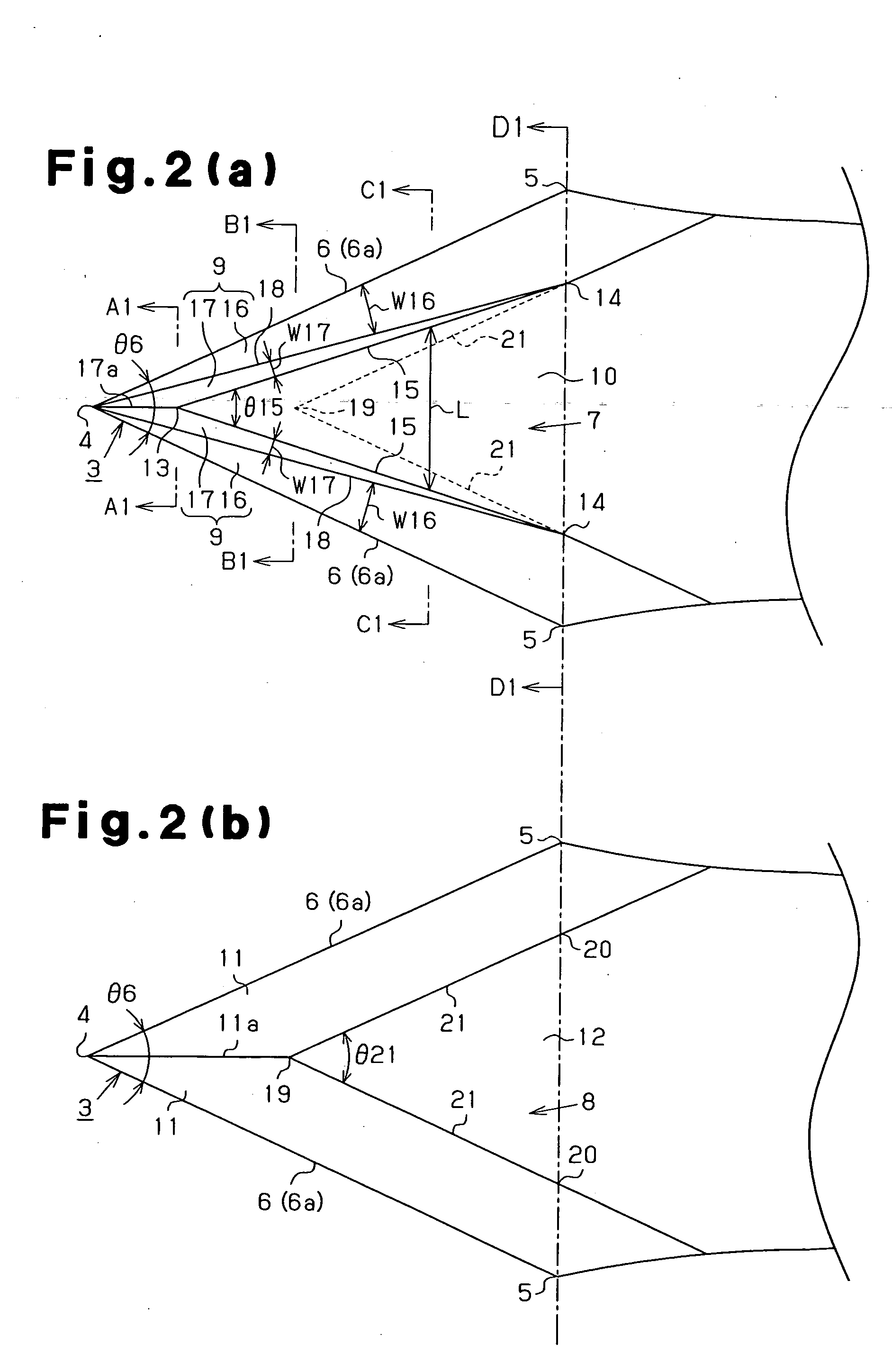
[0035] As illustrated in FIGS. 1(a) to 1(c), the medical knife is used surgically for dissecting eye tissue and includes a synthetic resin handle 1 and a metal plate 2. The plate 2 is attached to the handle 1 and is bent. A blade 3 is formed at a distal end of the plate 2. The plate 2 includes a front side 7 (a first side) and a rear side 8 (a second side). As shown in FIGS. 2(a) and 2(b), the front side 7 and the rear side 8 are defined between a pair of outer end lines 6 in an opposing manner. Each of the outer end lines 6 extends from a cutting point 4 (the distal end) to a corresponding one of proximal ends 5. A cutting edge 6a is formed along the entire portion of each outer end line 6. An angle θ6 defined by the opposing outer end lines 6 with respect to the cutting point 4 at each of the sides 7, 8 is not less than 15 degrees but not more tha...

Example

[0059] A medical knife according to a second embodiment of the present invention will be described with reference to FIGS. 5(a) to 7(d). The description will focus on the difference between the first embodiment and the second embodiment. In the second embodiment, the rear side 8 of the blade 3 is configured identically to the front side 7. Further, in each of the cutting surfaces 9 of the front side 7 and the rear side 8, the semi cutting angle β17 of the inner cutting surface 17 is larger than the semi cutting angle α16 of the outer cutting surface 16. The full cutting angle (semi cutting angle β17+semi cutting angle β17) of the inner cutting surfaces 17 of the corresponding cutting surfaces 9 of the front side 7 and the rear side 8 is thus larger than the full cutting angle (semi cutting angle α16+semi cutting angle α16) of the outer cutting surfaces 16 of the corresponding cutting surfaces 9 of the front side 7 and the rear side 8.

Example

[0060] A medical knife according to a third embodiment of the present invention will be described with reference to FIGS. 8(a) to 10(d). The description will focus on the difference between the first embodiment and the third embodiment. In the third embodiment, the outer cutting surface 16 of each first cutting surface 9 is configured differently than that of the first embodiment. That is, the outer cutting surface 16 of the third embodiment includes a pair of cutting surface sections 22, 23. The cutting surface section 22 includes the cutting edge 6a, while the cutting surface section 23 includes the concave line 18 between the outer cutting surface 16 and the inner cutting surface 17. A boundary line 24 is defined between the cutting surface sections 22, 23. In each first cutting surface 9, a semi cutting angle α22 is defined between the cutting surface section 22 of the outer cutting surface 16 and the hypothetical plane P6 extending between the cutting edges 6a. Likewise, a semi...


PUM


Abstract

A section of a first side of a blade between a cutting edge and a boundary line forms a cutting surface. An angle of a section of the cutting surface in the vicinity of the boundary line with respect to a hypothetical plane extending from the cutting edge and defined between the first and second sides of the blade is larger than an angle of a section of the cutting surface in the vicinity of the cutting edge with respect to the hypothetical plane. Therefore, the medical knife has an improved configuration such that the cutting performance of the knife is improved.

Description

BACKGROUND OF THE INVENTION [0001] The present invention relates to medical knifes used in surgeries for cutting biological tissue such as eye tissue. [0002]FIGS. 14 and 15 each show a conventional medical knife described in Japanese Laid-Open Patent Publication No. 2001-238890. The medical knife includes a pair of first cutting surfaces and a first intermediate surface 106c formed at a first side 106 of a blade 101. In each first cutting surface, an outer slanted surface 106a and an inner slanted surface 106b are defined. A hypothetical plane 105 extends between a pair of cutting edges 103 of the blade 101. The angle between the hypothetical plane 105 and each of the inner slanted surfaces 106b, that is a semi cutting angle of the inner slanted surface 106b, is smaller than the angle between the hypothetical plane 105 and each of the outer slanted surfaces 106a, that is a semi cutting angle of the outer slanted surface 106a. [0003] Also, a pair of opposed second cutting surfaces ar...

Claims


Application Information

Patent Timeline
IPC IPC(8): A61B17/3211A61F9/007A61F9/013
CPCA61F9/0133
Inventor ISOGIMI, KAZUHIKO
Owner KAI R&D CENT CO LTD
Why Eureka
Try Eureka