Apparatus and method for determining drilling fluid acoustic properties

a technology of acoustic properties and apparatus, which is applied in the field of downhole methods, can solve the problems of large degree of error in the estimated acoustic velocity and attenuation coefficient, the inability to accurately measure the acoustic velocity of drilling fluid, etc., to achieve the effect of improving the accuracy of standoff measurements

Active Publication Date: 2009-09-15
SCHLUMBERGER TECH CORP
View PDF138 Cites 46 Cited by
  • Summary
  • Abstract
  • Description
  • Claims
  • Application Information

AI Technical Summary

Benefits of technology

[0007]Exemplary embodiments of the present invention advantageously provide several technical advantages. For example, the apparatus and method of this invention enable the acoustic velocity and attenuation coefficient of drilling fluid in the borehole annulus to be determined in substantially real-time. Such real-time measurements provide for improved accuracy over prior art estimation techniques, which may improve the accuracy of standoff measurements and certain LWD data. As determined by exemplary embodiments of this invention, the drilling fluid acoustic properties are typically substantially independent of tool azimuth and eccentricity. The determined drilling fluid acoustic properties are also advantageously largely unaffected by the acoustic impedance of the drilling fluid and the acoustic impedance of the borehole itself.
[0008]Those of ordinary skill in the art will also recognize that in-situ monitoring of the variation in fluid velocity and attenuation coefficient tends to advantageously provide useful information for down-hole fluid and formation property characterization and for drilling process monitoring and diagnosis in real time.
[0009]Moreover, downhole tools in accordance with this invention may advantageously provide for more accurate standoff measurements. The radially offset sensors tend to provide for better sensitivity and resolution, as well as additional flexibility in transducer configuration and selection for both small and large standoffs. For example, one transducer may be configured to be more sensitive to small standoff values while the other may be better suited for large standoff detection. In certain applications, the two sensors may also be advantageously operated in different modes (e.g., pitch-catch or pulse-echo), be of different sizes, operate at different ultrasonic frequencies, and / or configured to have different focal depths.

Problems solved by technology

One drawback with such conventional standoff measurements is that the acoustic velocity of the drilling fluid can vary widely depending on the borehole conditions.
The presence or absence of cuttings, oil, water, and / or gas bubbles in the drilling fluid typically go unaccounted.
Depending on the type of drilling fluid and on the concentration of cuttings, oil, water, and / or gas bubbles therein, the degree of error to the estimated acoustic velocity and attenuation coefficient can be significant.
Moreover, as indicated above, such errors are not isolated, but can result in standoff distance errors, which can lead to subsequent LWD nuclear data weighting errors.
Acoustic velocity errors can also have a direct affect on sonic LWD data quality.
Errors in the acoustic velocity of the drilling fluid used in the model can therefore result in errors in formation shear velocity estimates.

Method used


Image

  • Apparatus and method for determining drilling fluid acoustic properties
  • Apparatus and method for determining drilling fluid acoustic properties
  • Apparatus and method for determining drilling fluid acoustic properties

Examples


Embodiment Construction

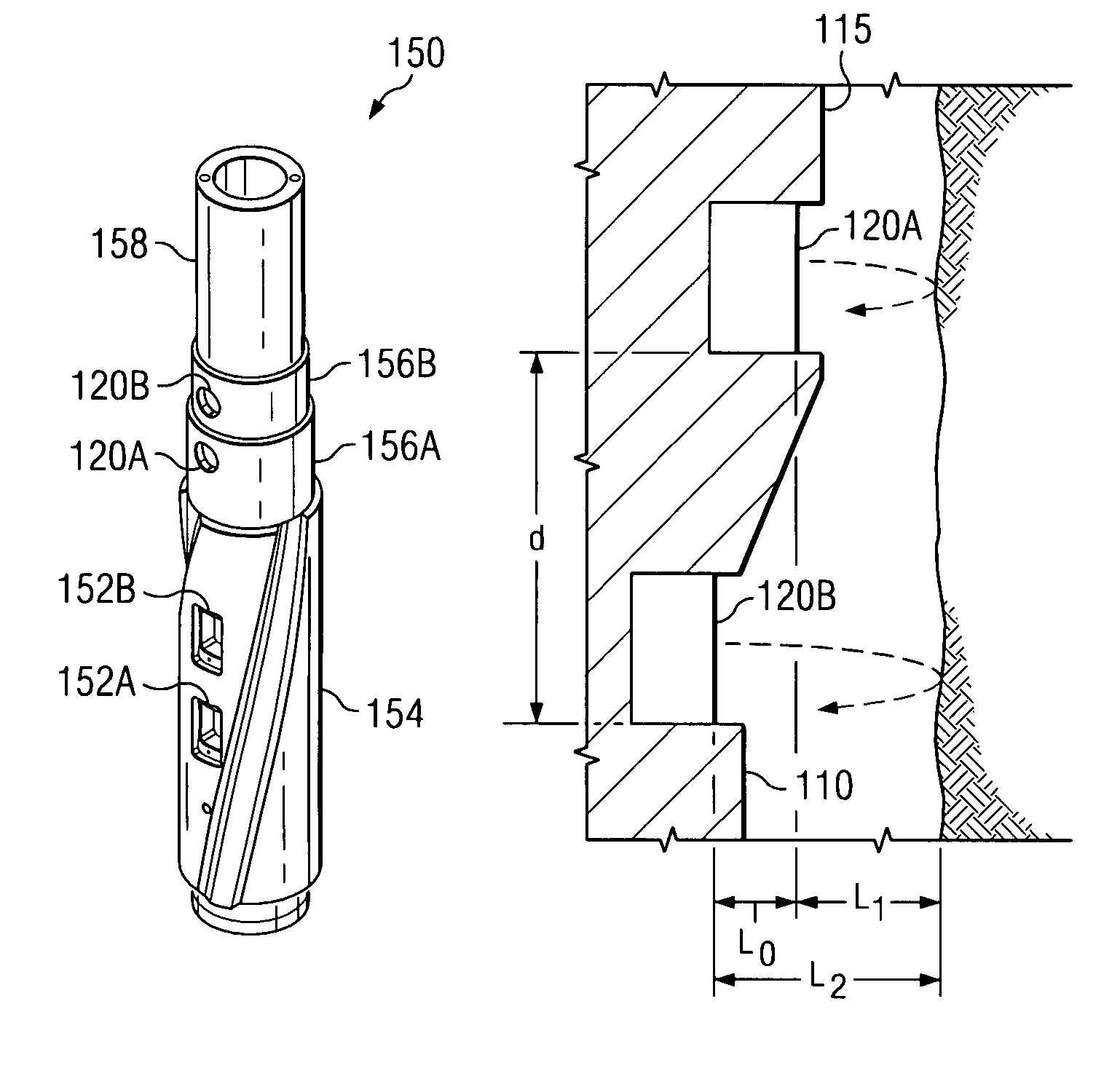
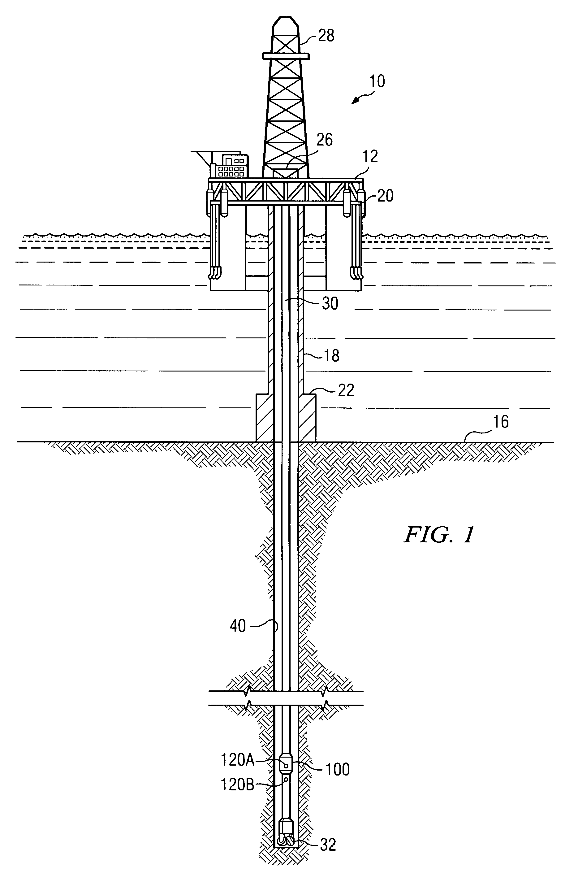
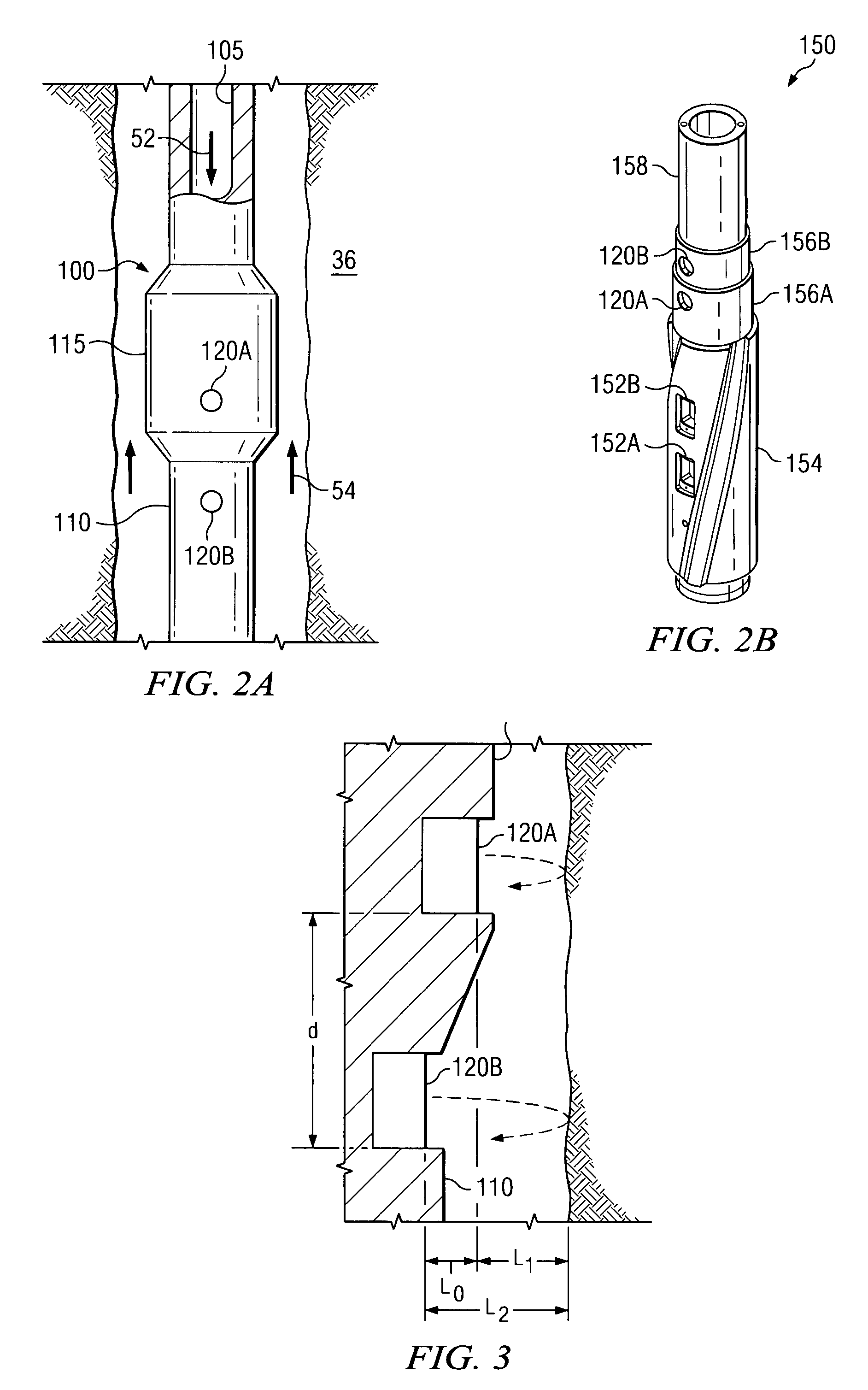
[0024]FIG. 1 depicts one exemplary embodiment of a measurement tool 100 according to this invention in use in an offshore oil or gas drilling assembly, generally denoted 10. In FIG. 1, a semisubmersible drilling platform 12 is positioned over an oil or gas formation (not shown) disposed below the sea floor 16. A subsea conduit 18 extends from deck 20 of platform 12 to a wellhead installation 22. The platform may include a derrick 26 and a hoisting apparatus 28 for raising and lowering the drill string 30, which, as shown, extends into borehole 40 and includes a drill bit 32 and a downhole measurement tool 100 having first and second radially and axially offset ultrasonic standoff sensors 120A and 120B. Drill string 30 may further include substantially any other downhole tools, including for example, a downhole drill motor, a mud pulse telemetry system, and one or more other sensors, such as a nuclear or sonic logging while drilling tool, for sensing downhole characteristics of the b...


PUM


Abstract

Aspects of this invention include a downhole tool having first and second radially offset ultrasonic standoff sensors and a controller including instructions to determine at least one of a drilling fluid acoustic velocity and a drilling fluid attenuation coefficient from the reflected waveforms received at the standoff sensors. The drilling fluid acoustic velocity may be determined via processing the time delay between arrivals of a predetermined wellbore reflection component at the first and second sensors. The drilling fluid attenuation coefficient may be determined via processing amplitudes of the predetermined wellbore reflection coefficients. The invention advantageously enables the acoustic velocity and attenuation coefficient of drilling fluid in the borehole annulus to be determined in substantially real-time.

Description

FIELD OF THE INVENTION[0001]The present invention relates generally to a downhole method of determining standoff and drilling fluid acoustic properties. More particularly, this invention relates to an apparatus and method for the downhole determination of acoustic velocity and attenuation coefficient of drilling fluid using first and second radially offset ultrasonic transducers.BACKGROUND OF THE INVENTION[0002]Logging while drilling (LWD) techniques are well-known in the downhole drilling industry and are commonly used to measure borehole and formation properties during drilling. Such LWD techniques include, for example, natural gamma ray, spectral density, neutron density, inductive and galvanic resistivity, acoustic velocity, acoustic caliper, downhole pressure, and the like. Many such LWD techniques require that the standoff distance between the logging sensors in the borehole wall be known with a reasonable degree of accuracy. For example, LWD nuclear / neutron techniques utilize...

Claims


Application Information

Patent Timeline
Patent Type & Authority Patents(United States)
IPC IPC(8): E21B47/00G01V1/00G01H5/00
CPCE21B47/082E21B47/01E21B47/085
Inventor HAN, WEI
Owner SCHLUMBERGER TECH CORP
Why Eureka
Try Eureka