
Shaping system, shaping method, and shaping control apparatus

a shaping control and shape technology, applied in the direction of computer control, program control, instruments, etc., can solve the problems of requiring a large amount of shaping time, affecting the shape of the object, so as to achieve the effect of facilitating the shaping of the obj

Active Publication Date: 2020-06-11
MIMAKI ENG
View PDF0 Cites 0 Cited by
  • Summary
  • Abstract
  • Description
  • Claims
  • Application Information

AI Technical Summary

Benefits of technology

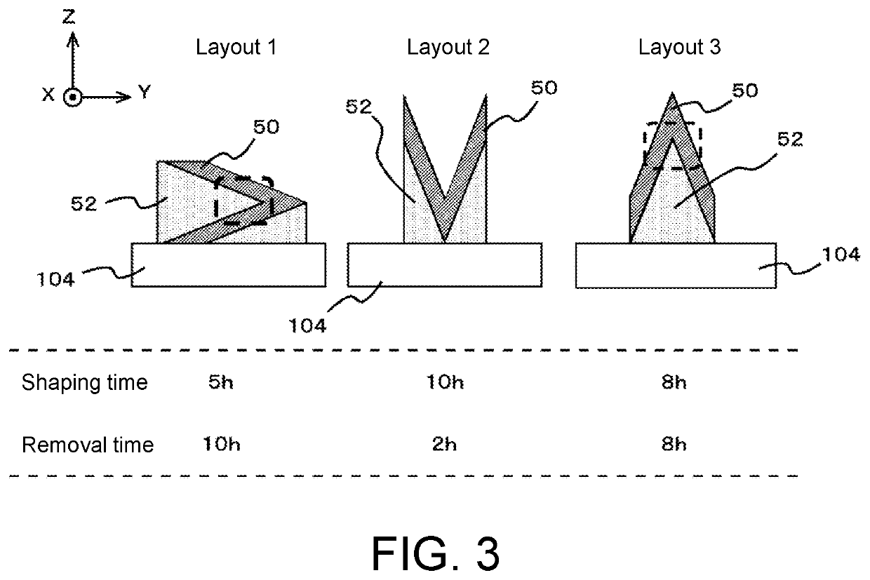
The present disclosure aims to improve the efficiency of shaping objects by reducing the time required for layering ink. One way to do this is to choose a layout that minimizes the shaping time, which dictates the orientation and other features of the shaped object during shaping. The disclosure's technical effect is that it enables quicker and more effective shaping of objects.

Problems solved by technology

When shaping a shaped object using a shaping device, for example, multiple layers of ink needs to be formed, and thus a great amount of time is sometimes required for shaping.
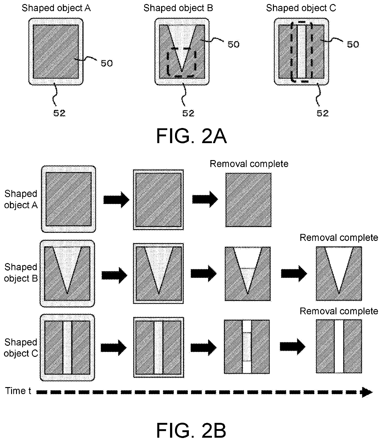
However, the inventor of the present application has found through intensive research that even if the shaping time is shortened, the time until all the work related to shaping is completed may become longer.
As a result, the time until all the work related to shaping is completed may become longer.

Method used


Image

  • Shaping system, shaping method, and shaping control apparatus
  • Shaping system, shaping method, and shaping control apparatus
  • Shaping system, shaping method, and shaping control apparatus

Examples


Embodiment Construction

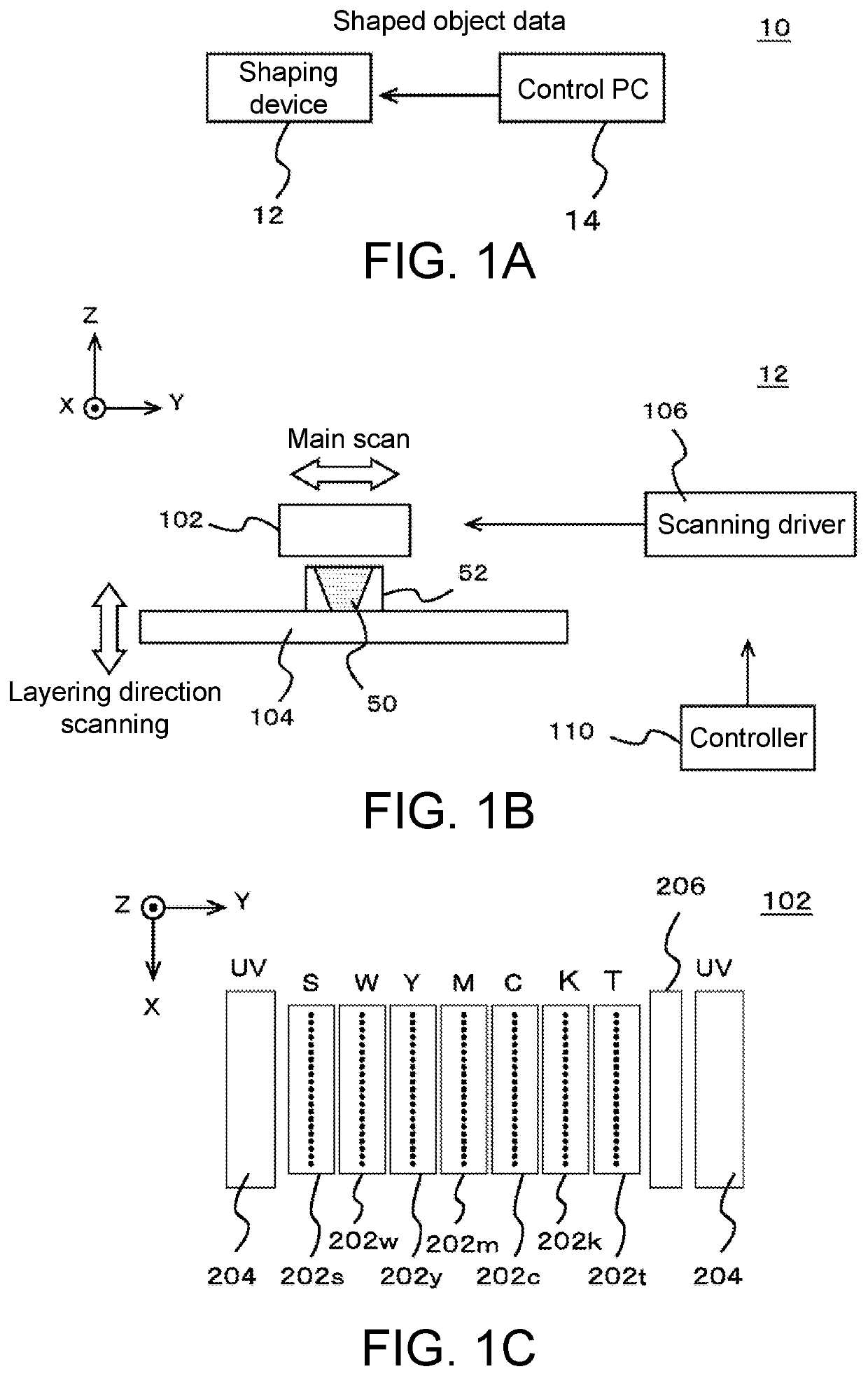
[0027]Hereinafter, an embodiment according to the present disclosure will be described with reference to the drawings. FIGS. 1A to 1C show an example of a shaping system 10 according to an embodiment of the present disclosure. FIG. 1A shows an example of a configuration of the shaping system 10. In the present example, the shaping system 10 is a shaping system that shapes a stereoscopic shaped object, and includes a shaping device 12 and a control PC 14.

[0028]The shaping device 12 is an example of a shaping portion that performs an operation of shaping a shaped object. In the present example, the shaping device 12 is a full-color shaping device capable of shaping a shaped object colored in full color, and receives shaped object data, which is data indicating a shaped object to be shaped, from the control PC 14, and shapes the shaped object based on the shaped object data. Furthermore, the shaping device 12 shapes a shaped object in accordance with the control of the control PC 14. M...


PUM

PropertyMeasurementUnit
timeaaaaaaaaaa
shaping timeaaaaaaaaaa

Abstract

A shaping system for shaping a stereoscopic shaped object, the shaping system including a shaping device serving as a shaping portion and a control PC serving as a shaping controller. At a time of shaping a shaped object, the shaping device further forms a support layer that supports at least a part of the shaped object being shaped, and the control PC predicts a support layer removal time which is a time required for removing the support layer after formation of the shaped object and the support layer in the shaping device is completed.

Description

CROSS REFERENCE TO RELATED APPLICATIONS[0001]This application claims the priority benefit of Japanese Patent Application No. 2018-229680, filed on Dec. 7, 2018. The entirety of the above-mentioned patent application is hereby incorporated by reference herein and made a part of this specification.TECHNICAL FIELD[0002]The present disclosure relates to a shaping system, a shaping method, and a shaping control apparatus.DESCRIPTION OF THE BACKGROUND ART[0003]Conventionally, a shaping device (3D printer) for shaping a shaped object using an inkjet head is known (see e.g., Japanese Unexamined Patent Publication No. 2015-071282 (Patent Literature 1)). In such a shaping device, for example, the shaped object is shaped through a layered shaping method by overlapping a plurality of layers of ink formed by an inkjet head.[0004]Patent Literature 1: Japanese Unexamined Patent Publication No. 2015-071282SUMMARY[0005]When shaping a shaped object using a shaping device, for example, multiple layers...

Claims


Application Information

Patent Timeline
Patent Type & Authority Applications(United States)
IPC IPC(8): B29C64/393B29C64/40B33Y50/02G05B19/4099
CPCB29C64/40B29C64/393G05B19/4099G05B2219/49007B33Y50/02G05B2219/31429B33Y30/00B33Y40/20
Inventor HARAYAMA, KENJI
Owner MIMAKI ENG
Learn More