Numerical control device

a control device and numerical technology, applied in the direction of electric programme control, program control, instruments, etc., can solve the problem of lowering the machining precision to exceed the permissible range, and achieve the effect of shortening the machining tim

Active Publication Date: 2020-06-11
FANUC LTD
View PDF0 Cites 1 Cited by
  • Summary
  • Abstract
  • Description
  • Claims
  • Application Information

AI Technical Summary

Benefits of technology

[0012]With the numerical control device according to the present invention, shortening of the machining time is easy.

Problems solved by technology

However, with a change in such a limit value, there is a risk of lowering the machining precision to exceed the permissible range.

Method used


Image

  • Numerical control device
  • Numerical control device
  • Numerical control device

Examples


Embodiment Construction

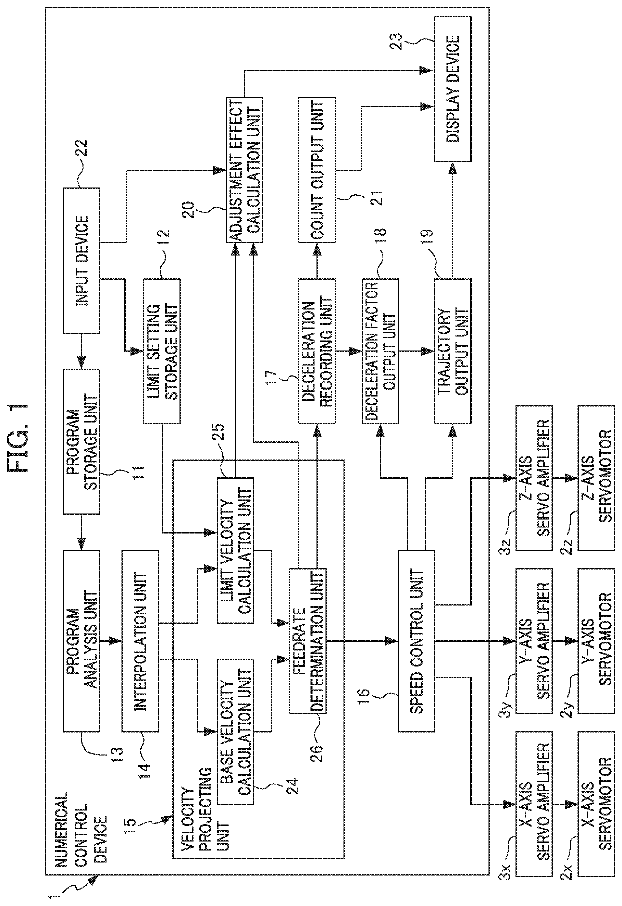
[0019]Hereinafter, an embodiment of the present invention will be explained while referencing the drawings. FIG. 1 is a block diagram showing the configuration of a numerical control device 1 according to an embodiment of the present invention.

[0020]The numerical control device 1 is a device for controlling a machine tool, and causes the tool to move along a movement path decided by a machining program. More specifically, the numerical control device 1 controls servo amplifiers 3x, 3y and 3z which drive each of servomotors 2x, 2y and 2z of drive axes in the mutually perpendicular X, Y and Z directions positioning the tool.

[0021]The numerical control device 1 includes: a program storage unit 11, limit setting storage unit 12, program analysis unit 13, interpolation unit 14, velocity projecting unit 15, speed control unit 16, deceleration recording unit 17, deceleration factor output unit 18, trajectory output unit 19, adjustment effect calculation unit 20 and count output unit 21, as...


PUM


Abstract

A numerical control device according to the present invention is for a machine tool which causes a tool to move along a movement path decided according to a machining program, and includes: a limit setting storage unit in which limit values of a plurality of parameter related to movement of the tool are set; a limit velocity calculation unit which calculates a plurality of limit velocities which are movement velocities of the tool, which respectively correspond to the limit values of the plurality of parameters at each position of the movement path; a feedrate determination unit which defines a minimum value among an ideal velocity of the tool and the plurality of limit velocities at each position on the movement path as a feedrate of the tool at each position on the movement path; and an adjustment effect calculation unit which calculates variation in movement time required in order to cause the tool to move an entirety of the movement path at the feedrate, in a case of changing the limit value of the parameter.

Description

[0001]This application is based on and claims the benefit of priority from Japanese Patent Application No. 2018-230724, filed on 10 Dec. 2018, the content of which is incorporated herein by reference.BACKGROUND OF THE INVENTIONField of the Invention[0002]The present invention relates to a numerical control device.Related Art[0003]A machine tool causes a tool to move along a movement path which is decided by a machining program. At this time, if increasing the acceleration of the tool, there are cases where error arises in movement of the tool, and the tool is not made to accurately move on the required movement path. For this reason, as described in Patent Document 1, for example, technology has been known for performing deceleration control to decelerate the tool so that the acceleration of the tool does not exceed a predetermined limit value, at a position at which the movement path curves, for example.[0004]In addition, other than acceleration, it has been known that it is possib...

Claims


Application Information

Patent Timeline
Patent Type & Authority Applications(United States)
IPC IPC(8): G05B19/4155
CPCG05B19/4155G05B2219/35521G05B19/19G05B2219/35349G05B2219/43203G05B2219/43065G05B2219/43058
Inventor KOIDE, NAOYA
Owner FANUC LTD
Why Eureka
Try Eureka