Sealing element

a technology of sealing element and sealing tube, which is applied in the direction of sealing/packing, mechanical equipment, and borehole/well accessories, etc., can solve the problems of reducing the pressure in the pipeline and the potential contamination of the water being carried in the pipeline, and achieves the effect of easy drawing into the defects of the pipelin

Active Publication Date: 2020-06-25
QINOV8 UK LTD
View PDF0 Cites 2 Cited by
  • Summary
  • Abstract
  • Description
  • Claims
  • Application Information

AI Technical Summary

Benefits of technology

[0035]The pipeline may be downstream of a water meter and the method may include the step of turning a stop cock associated with the water meter off, removing a closure component from and opening of the pipeline that allows access to the inside of the pipeline, inserting a sealing element into the pipeline through the opening, replacing the closure apparatus and turning the stop cock off to allow fluid to flow in the pipeline down stream of the stop cock. This provides the advantage that when the sealing element is in the pipeline the pipeline is full of fluid. It is advantageous that there is not significant air in the pipeline.
[0036]The sealing element of the invention has a density less than or equal to the density of the fluid through which it is to travel, meaning that it is buoyant in that fluid. The buoyancy provides an improved sealing element which is more easily drawn into defects within a pipeline.

Problems solved by technology

Leaks in water pipes can lead to reduced pressure in the pipeline as well as potential contamination of the water being carried in the pipes.

Method used


Image

  • Sealing element
  • Sealing element
  • Sealing element

Examples


Embodiment Construction

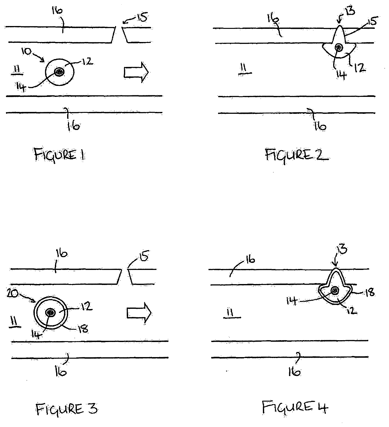
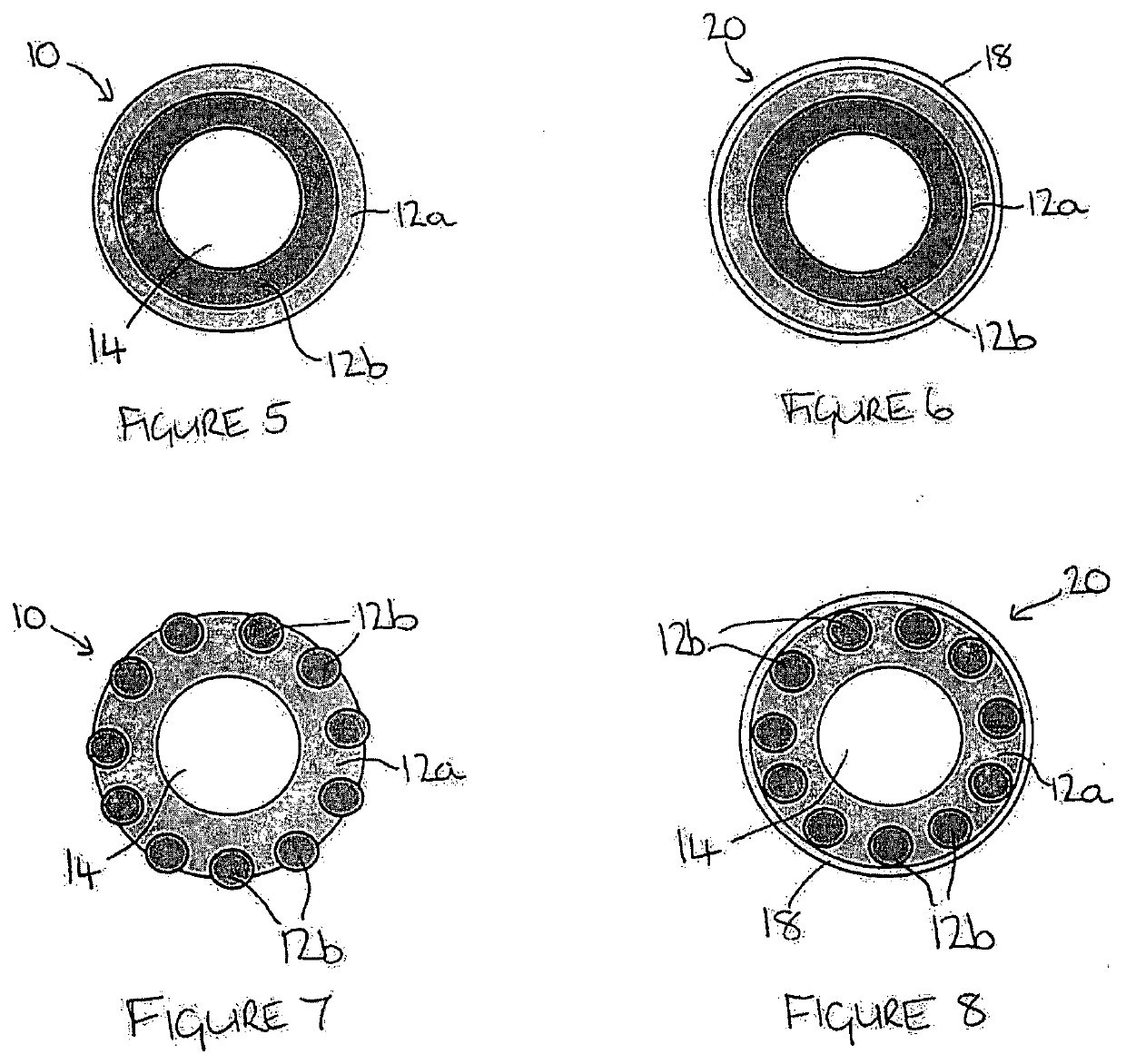
[0049]FIG. 1 illustrates a cross-sectional view of an example of a substantially spherical sealing element 10 according to a first embodiment of the invention, shown inside a pipeline 16, in which there is a defect or hole 15.

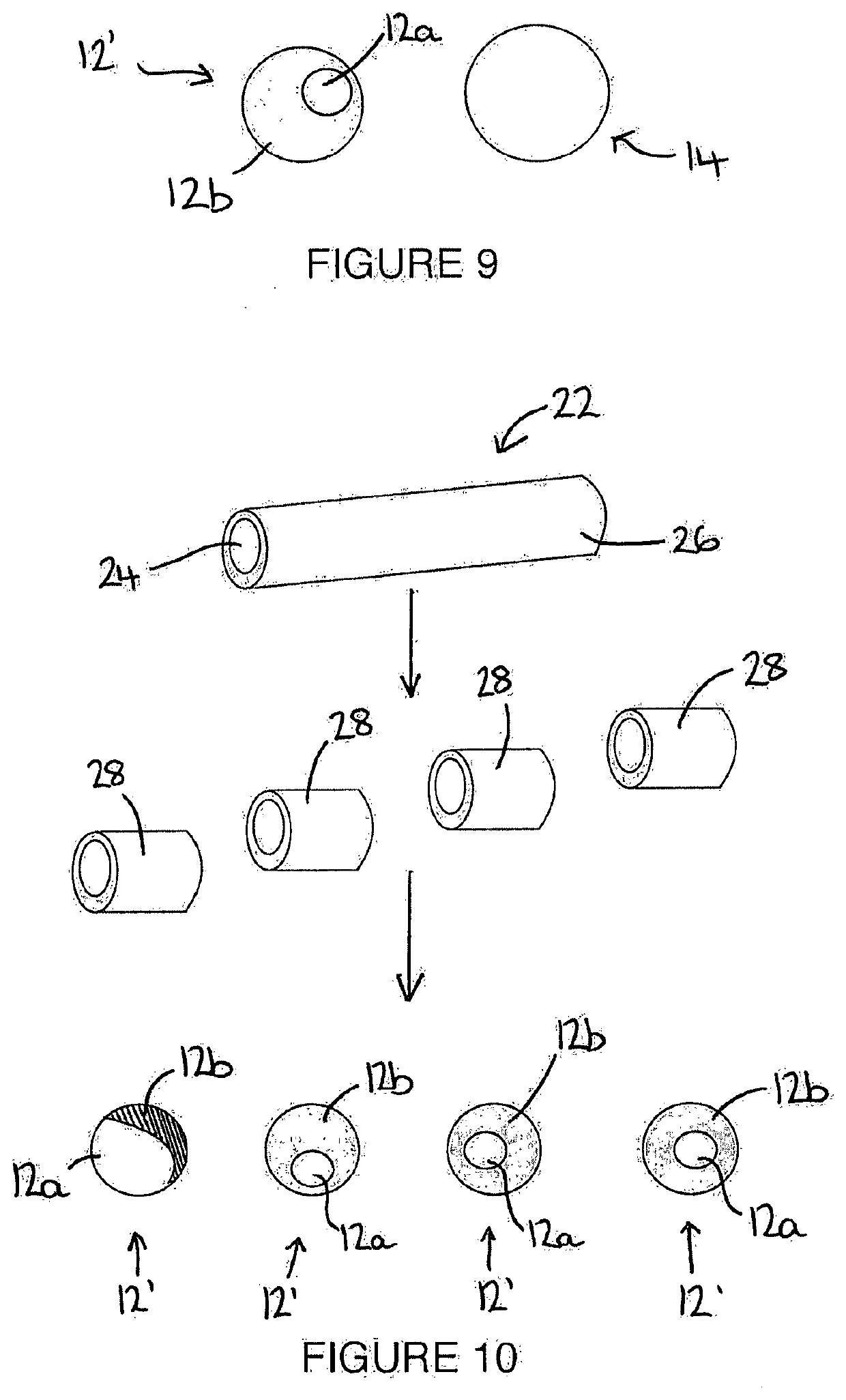
[0050]The sealing element 10 includes a buoyant core 14 surrounded by a coating of epoxy putty 12. The putty changes state over time from malleable to substantially solid.

[0051]In this example, the buoyant core 14 is a polystyrene sphere with a diameter of between 1 mm and 5 mm. The total diameter of the sealing element is preferably in the range 5 to 10 mm.

[0052]A fluid 11, typically water, flows along the pipeline 16 in the direction of the arrow. The sealing element 10 is deployed into the pipeline 16 upstream of the hole 15. The sealing element 10 has a density substantially equal to the fluid being carried by the pipeline 16, meaning that the sealing element 10 travels easily along with the fluid 11.

[0053]The putty 12 comprises a two-part epoxy resin and t...


PUM

PropertyMeasurementUnit
densityaaaaaaaaaa
diameteraaaaaaaaaa
diameteraaaaaaaaaa

Abstract

A sealing element (10) for use in a fluid-carrying pipeline (16) comprising a substantially central core (14) surrounded by a coating (12). The outer coating (12) is adapted to perform a partial extrusion through an opening (15) in a pipeline wall (16) to seal the opening (15). The density of the sealing element (10) is substantially the same as the density of the fluid (11) in the pipeline (16). The coating (12) comprises a two-part epoxy putty, and the core (14) is formed from a deformable material. A method of making the sealing element is also disclosed.

Description

FIELD OF THE INVENTION[0001]The present invention relates to apparatus for sealing leaks in fluid-carrying ducts or pipelines.BACKGROUND OF THE INVENTION[0002]Pipes carrying fluid, such as water, are usually located underground. Leaks in water pipes can lead to reduced pressure in the pipeline as well as potential contamination of the water being carried in the pipes.[0003]It is known from EP2902690 to use an untethered, sphere-shaped sensor unit adapted to roll along the interior surface of a water-carrying pipeline. The sensor unit uses acoustic sensors to detect leaks and record their location, so that they can be investigated and repaired from the surface.[0004]It is known from GB2465487 to both detect and seal leaks in oil pipelines using remote sealing elements which are deployed upstream of the leak and carried to the leak site in the fluid within the pipe. The sealing elements are designed such that they are drawn into the defect and subsequently seal the leak by blocking th...

Claims


Application Information

Patent Timeline
Patent Type & Authority Applications(United States)
IPC IPC(8): E21B33/138F16L55/16F16L55/164B29C48/18B29B9/12B29B9/16
CPCF16L55/164F16L55/1612B29C48/18B29B9/12E21B33/138C09J163/00B29B9/16B29B2009/163B29B2009/166E21B29/10E21B43/25F16L55/162
Inventor QUINN, MICHAELQUINN, MARK
Owner QINOV8 UK LTD
Why Eureka
Try Eureka