
Acoustic wave device and method for manufacturing acoustic wave device

Active Publication Date: 2020-07-09
MURATA MFG CO LTD
View PDF0 Cites 0 Cited by
  • Summary
  • Abstract
  • Description
  • Claims
  • Application Information

AI Technical Summary

Benefits of technology

This patent is about a method for making acoustic devices that can be smaller while maintaining good quality. The method involves using a special process to create smaller components without compromising their performance. The result is that the acoustic devices can be made smaller while still being very effective. This technique can be used to make various types of acoustic devices, such as filters and sensors.

Problems solved by technology

WO 2016 / 147688, when the capacitor that is a discrete element is used or the capacitor is formed on a surface of a substrate (on the second main surface of the piezoelectric layer), there is a problem in that the size thereof becomes large.
However, when the capacitor is integrally provided with the acoustic wave device, there is a problem in that an unnecessary capacitance component affects an IDT electrode of the acoustic wave device due to influence of the capacitor.
As a result, characteristics of the acoustic wave device deteriorate.

Method used


Image

  • Acoustic wave device and method for manufacturing acoustic wave device
  • Acoustic wave device and method for manufacturing acoustic wave device
  • Acoustic wave device and method for manufacturing acoustic wave device

Examples


first preferred embodiment

(1) Overall Configuration of Acoustic Wave Device

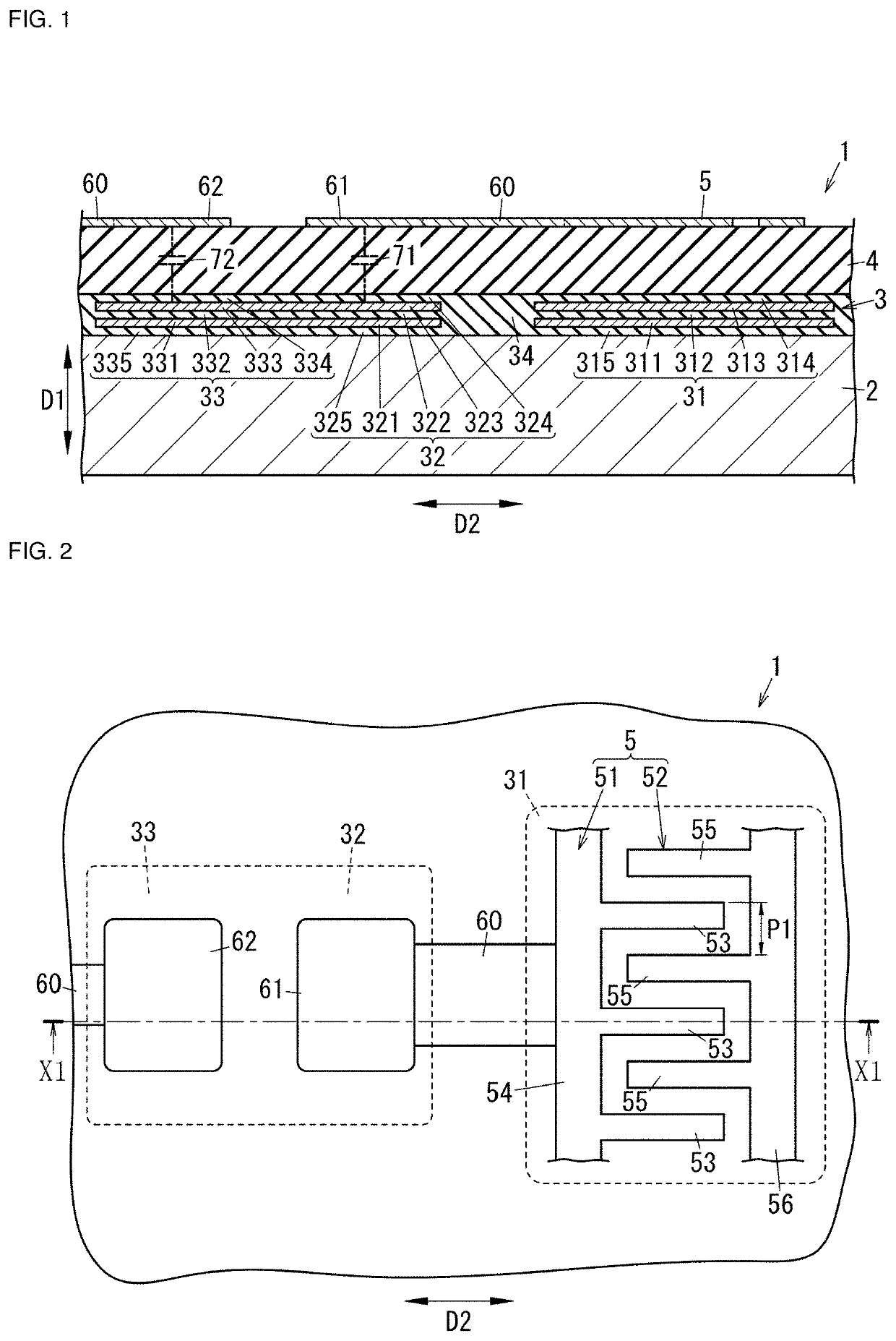
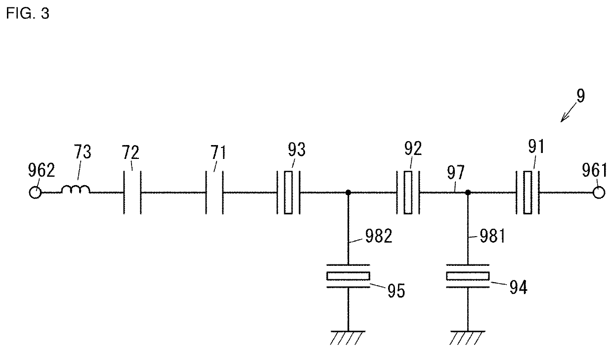
[0022]As shown in FIG. 1 and FIG. 2, an acoustic wave device 1 according to a first preferred embodiment includes a substrate 2, an intermediate layer 3, a piezoelectric layer 4, an interdigital transducer (IDT) electrode 5, and a plurality of electrodes 61 and 62 (two electrodes in the shown example). The acoustic wave device 1 is an acoustic wave device using a plate wave.

[0023]The intermediate layer 3 includes a first acoustic impedance layer 31 and a plurality of second acoustic impedance layers 32 and 33. The first acoustic impedance layer 31 has a laminated structure including a plurality of first high acoustic impedance layers 311 and 313 and a plurality of first low acoustic impedance layers 312, 314, and 315, and faces the IDT electrode 5 in a thickness direction (first direction D1) of the substrate 2. The second acoustic impedance layer 32 has a laminated structure including a plurality of second high acoustic impedance lay...

second preferred embodiment

[0101]As shown in FIG. 6, an acoustic wave device 1a according to a second preferred embodiment of the present invention is different from the acoustic wave device 1 according to the first preferred embodiment (see FIG. 2) in that the acoustic wave device 1a includes an inductor 8 (a third acoustic impedance layer 37) together with the IDT electrode 5. The same or similar elements as those in the acoustic wave device 1 according to the first preferred embodiment are denoted by the same reference signs, and description thereof will be omitted. In addition, FIG. 7 is a cross-sectional view taken along a line X2-X2 in FIG. 6.

[0102]As shown in FIG. 6 and FIG. 7, the acoustic wave device 1a according to the second preferred embodiment includes the substrate 2, an intermediate layer 3a , the piezoelectric layer 4, the IDT electrode 5, and a plurality of electrodes 63 and 64 (two electrodes in the shown example). Note that since the substrate 2, the piezoelectric layer 4, and the IDT elect...


PUM


Abstract

An acoustic wave device includes a first acoustic impedance layer and a second acoustic impedance layer, an IDT electrode, and an electrode. At least a portion of the IDT electrode overlaps the first acoustic impedance layer. At least a portion of the electrode overlaps the second acoustic impedance layer. In each of the first acoustic impedance layer and the second acoustic impedance layer, at least one of a high acoustic impedance layer and a low acoustic impedance layer is a conductive layer. A capacitor is formed by using the conductive layer of the second acoustic impedance layer and the electrode. The conductive layer in the first acoustic impedance layer is electrically insulated from the conductive layer in the second acoustic impedance layer.

Description

CROSS REFERENCE TO RELATED APPLICATIONS[0001]This application claims the benefit of priority to Japanese Patent Application No. 2017-186736 filed on Sep. 27, 2017 and is a Continuation Application of PCT Application No. PCT / JP2018 / 035555 filed on Sep. 26, 2018. The entire contents of each application are hereby incorporated herein by reference.BACKGROUND OF THE INVENTION1. Field of the Invention[0002]The present invention relates to an acoustic wave device and a method for manufacturing an acoustic wave device, and more particularly to an acoustic wave device to be used in a resonator or a filter and a method for manufacturing an acoustic wave device to be used in a resonator or a filter.2. Description of the Related Art[0003]Conventionally, an acoustic wave device using an acoustic reflection layer (acoustic impedance layer) has been known (see, for example, International Publication No. WO 2016 / 147688).[0004]The acoustic wave device described in International Publication No. WO 20...

Claims


Application Information

Patent Timeline
IPC IPC(8): H03H9/54H03H3/02H03H9/02H03H9/56
CPCH03H9/02228H03H9/568H03H3/02H03H9/542H03H9/175H03H9/605H03H9/25H03H9/64H03H3/08
Inventor OMURA, MASASHI
Owner MURATA MFG CO LTD
Learn More