Stator, stepping motor, timepiece movement, timepiece, and manufacturing method of stator
- Summary
- Abstract
- Description
- Claims
- Application Information
AI Technical Summary
Benefits of technology
Problems solved by technology
Method used
Image

Examples
first embodiment
Timepiece and Movement
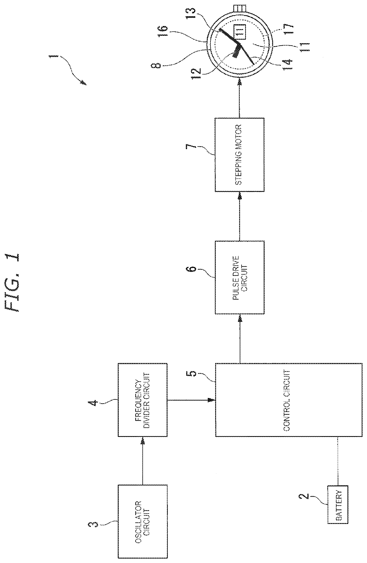
[0053]FIG. 1 is a block diagram illustrating a timepiece according to a first embodiment.
[0054]As illustrated in FIG. 1, a timepiece 1 includes a battery 2, an oscillator circuit 3, a frequency divider circuit 4, a control circuit 5, a pulse drive circuit 6, a stepping motor 7, and an analog timepiece unit 8.
[0055]The analog timepiece unit 8 includes a train wheel 11, an hour hand 12, a minute hand 13, a second hand 14, a calendar display unit 15, a timepiece case 16, and a movement 17 (timepiece movement). In the present embodiment, if one of the hour hand 12, the minute hand 13, and the second hand 14 is not specified, all of these will be referred to as “indicating hands”. The oscillator circuit 3, the frequency divider circuit 4, the control circuit 5, the pulse drive circuit 6, the stepping motor 7, and the train wheel 11 are configuration elements of the movement 17.
[0056]For example, the battery 2 is a so-called button battery such as a silver oxide batt...
second embodiment
Configuration of Stepping Motor
[0104]FIG. 7 is a plan view schematically illustrating a stepping motor according to a second embodiment. FIG. 8 is a sectional view of the stator which is taken along line in FIG. 7.
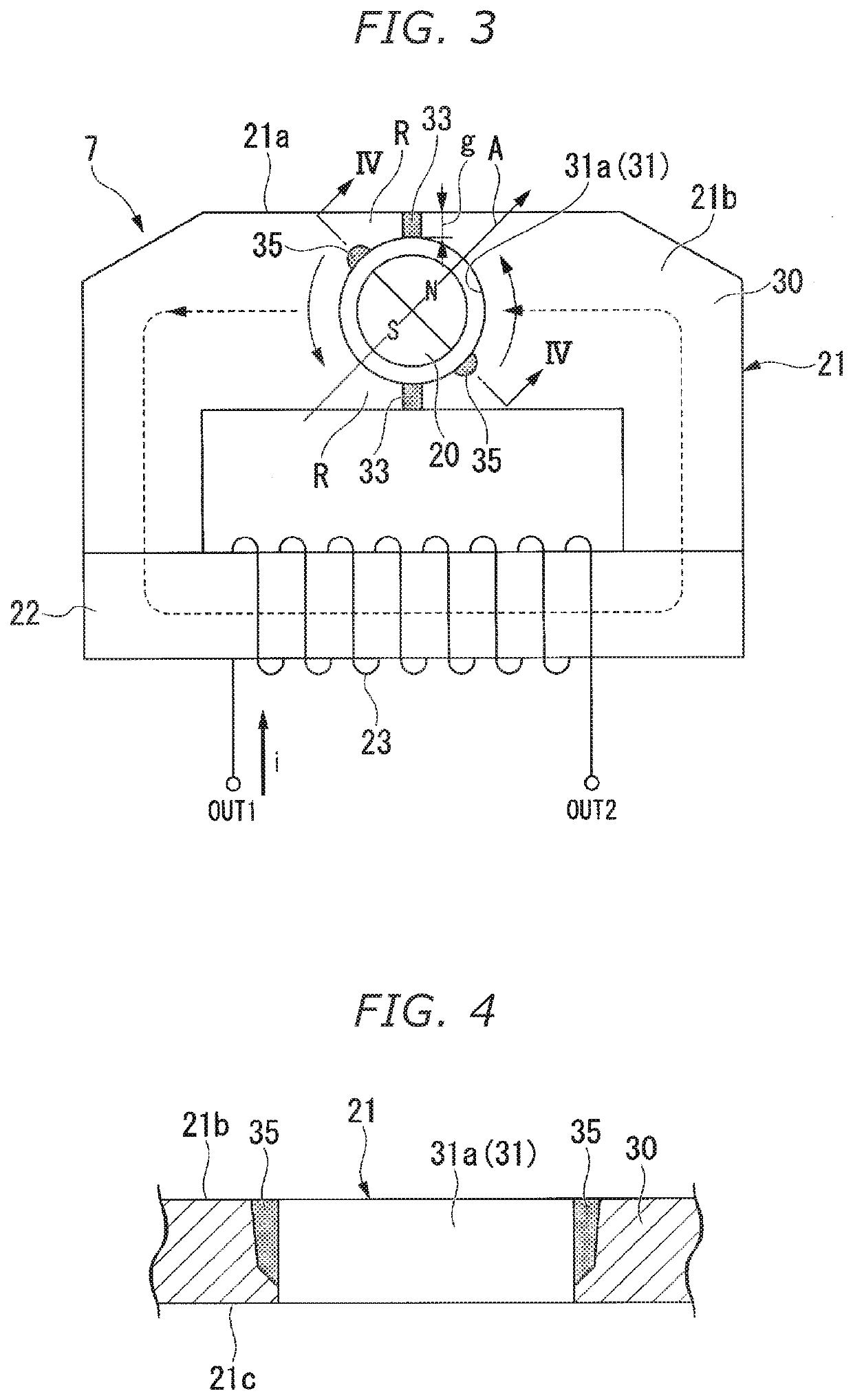
[0105]In the first embodiment illustrated in FIG. 3, the non-magnetic portion 35 is disposed on the inner peripheral surface 31a of the through-hole 31. In contrast, in the second embodiment illustrated in FIG. 7, a non-magnetic portion 135 is disposed away from the through-hole 31. In this regard, the second embodiment is different from the first embodiment. Configurations other than those described below are the same as those according to the first embodiment.
[0106]As illustrated in FIG. 7, the non-magnetic portion 135 is formed in a circular shape on the first main surface 21b of the stator 21.
[0107]As illustrated in FIG. 8, the non-magnetic portion 135 is formed so that a cross-sectional area of a cross section orthogonal to the thickness direction of the stator 21 gra...
third embodiment
Configuration of Stepping Motor
[0109]FIG. 9 is a plan view schematically illustrating a stepping motor according to a third embodiment.
[0110]According to the first embodiment illustrated in FIG. 3, the magnetoresistive portion 33 is formed to have the lower magnetic permeability than the magnetic body 30. In contrast, according to the third embodiment illustrated in FIG. 9, a magnetoresistive portion 233 is a narrow portion formed by disposing an outer notch 237 in the outer edge 21a of the stator 21. In this regard, the third embodiment is different from the first embodiment. Configurations other than those described below are the same as those according to the first embodiment.
[0111]As illustrated in FIG. 9, the pair of outer notches 237 is formed in the outer edge 21a of the stator 21. Each of the pair of outer notches 237 is disposed on a side opposite to the through-hole 31 across the magnetic path R The outer notch 237 locally reduces a cross-sectional area of the magnetic pat...
PUM
| Property | Measurement | Unit |
|---|---|---|
| Length | aaaaa | aaaaa |
| Power | aaaaa | aaaaa |
| Depth | aaaaa | aaaaa |
Abstract
Description
Claims
Application Information
 - Generate Ideas
- Intellectual Property
- Life Sciences
- Materials
- Tech Scout
- Unparalleled Data Quality
- Higher Quality Content
- 60% Fewer Hallucinations
Browse by: Latest US Patents, China's latest patents, Technical Efficacy Thesaurus, Application Domain, Technology Topic, Popular Technical Reports.
© 2025 PatSnap. All rights reserved.Legal|Privacy policy|Modern Slavery Act Transparency Statement|Sitemap|About US| Contact US: help@patsnap.com