Temperature adjustment apparatus, intermediary apparatus, load apparatus, and refrigeration cycle apparatus

a technology of temperature adjustment apparatus and load apparatus, which is applied in the direction of lighting and heating apparatus, ducting arrangements, heating types, etc., can solve the problems of insufficient performance, affecting the efficiency of operation, and affecting the comfort of users, so as to improve the temperature adjustment performance and maintain the energy saving performance of the refrigeration cycle apparatus.

Active Publication Date: 2020-07-23
MITSUBISHI ELECTRIC CORP
View PDF0 Cites 0 Cited by
  • Summary
  • Abstract
  • Description
  • Claims
  • Application Information

AI Technical Summary

Benefits of technology

[0011]Since the temperature adjustment apparatus in the present disclosure can finely adjust a temperature of liquid refrigerant supplied to an indoor he

Problems solved by technology

Therefore, the temperature of the room is varied, comfort is compromised, and operation efficiency is lowered.
When loads are different among the plurality of rooms, a temperature of water and the load do not match in some rooms, and i

Method used


Image

  • Temperature adjustment apparatus, intermediary apparatus, load apparatus, and refrigeration cycle apparatus
  • Temperature adjustment apparatus, intermediary apparatus, load apparatus, and refrigeration cycle apparatus
  • Temperature adjustment apparatus, intermediary apparatus, load apparatus, and refrigeration cycle apparatus

Examples


first embodiment

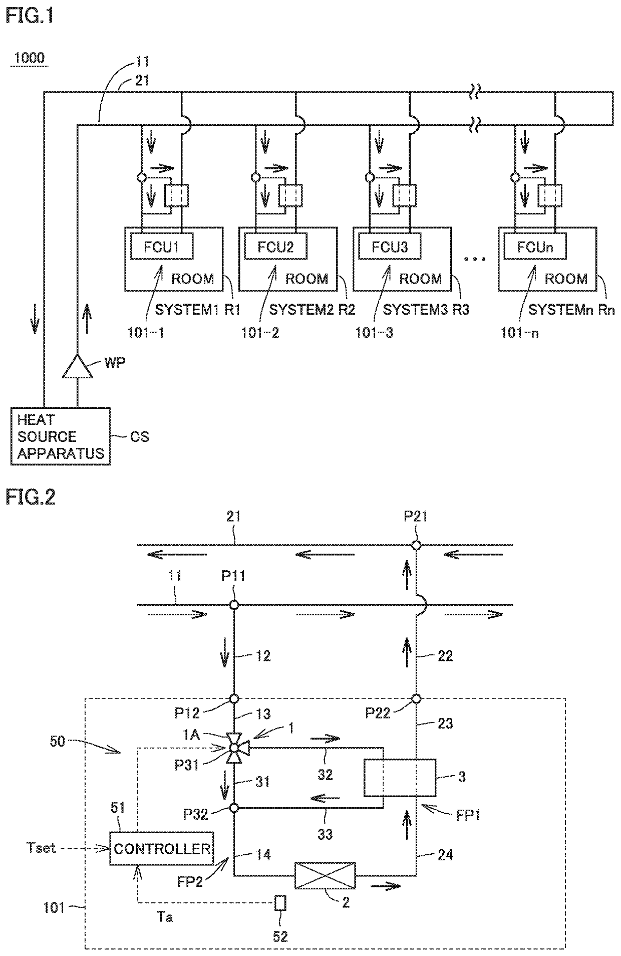
[0038]FIG. 1 is a diagram showing an overall configuration of an air-conditioning system to which a temperature adjustment apparatus in the present embodiment is applied. Referring to FIG. 1, an air-conditioning system 1000 includes a heat source apparatus CS, a pump WP, load apparatuses 101-1 to 101-n, and a pipe.

[0039]Heat source apparatus CS is an apparatus configured to cool or heat a heating medium to be supplied to load apparatuses 101-1 to 101-n. The heating medium is supplied to load apparatuses 101-1 to 101-n from heat source apparatus CS through a trunk pipe 11 for supply of the heating medium from heat source apparatus CS to load apparatuses 101-1 to 101-n and returned to heat source apparatus CS from load apparatuses 101-1 to 101-n through a trunk pipe 21 that recovers the heating medium from load apparatuses 101-1 to 101-n to heat source apparatus CS. Pump WP circulates the heating medium that passes through trunk pipe 11 and trunk pipe 21 through air-conditioning syste...

second embodiment

[0069]FIG. 9 is a diagram showing a circuit configuration of a load apparatus 102 and an intermediary apparatus 103 and a flow of a heating medium according to a second embodiment.

[0070]Air-conditioning system 1000 according to the second embodiment includes heat source apparatus CS, pump WP, a plurality of load apparatuses 102-1 to 102-n, a plurality of intermediary apparatuses 103-1 to 103-n, and a pipe, and temperature adjustment apparatus 50 accommodated in load apparatus 101 according to the first embodiment is accommodated in intermediary apparatus 103.

[0071]Load apparatus 102 is connected to heat source apparatus CS with intermediary apparatus 103 being interposed, and load apparatus 102 and intermediary apparatus 103 are connected to each other through pipe 14 and pipe 24. Intermediary apparatus 103 is connected to trunk pipe 11 and trunk pipe 21 through connection pipe 12 and connection pipe 22. Load apparatus 102 includes indoor heat exchanger 2, a pipe 14C that connects a...

third embodiment

[0085]FIG. 13 is a diagram showing a circuit configuration of a load apparatus and a flow of a heating medium according to a third embodiment. Referring to FIG. 13, a load apparatus 104 includes a temperature adjustment apparatus 50F and indoor heat exchanger 2. Temperature adjustment apparatus 50F includes a pipe FP1A and a pipe FP2A through which the heating medium flows, flow rate regulator 1, and second heat exchanger 3. Pipe FP2A is configured to be branched into first branch pipe 32 and second branch pipe 31, the first branch pipe and the second branch pipe thereafter being merged again. Flow rate regulator 1 includes flow rate distribution valve 1A. Pipe FP2A includes pipes 23 and 24 and branch pipes 31, 32, and 33. Pipe FP1A includes pipes 13 and 14. Though not shown, controller 51 and temperature sensor 52 are also arranged as in FIG. 2.

[0086]Pipe 13 guides the heating medium from liquid inlet P12 of load apparatus 104 to second heat exchanger 3. Pipe 14 connects second hea...


PUM


Abstract

The temperature adjustment apparatus includes a first pipe, a second pipe, the second pipe being branched into a first branch pipe and a second branch pipe, the first branch pipe and the second branch being thereafter merged again, a second heat exchanger in which heat is exchanged between the heating medium that flows through the first branch pipe and the heating medium that flows through the first pipe, and a flow rate regulator configured to change a flow rate of the heating medium that flows through the first branch pipe and a flow rate of the heating medium that flows through the second branch pipe. The second pipe is a pipe configured to supply the heating medium from the heat source apparatus to the indoor heat exchanger and the first pipe is a pipe configured to return the heating medium from the indoor heat exchanger to the heat source apparatus.

Description

TECHNICAL FIELD[0001]The present invention relates to a temperature adjustment apparatus, and particularly to a temperature adjustment apparatus configured to adjust a temperature of a liquid medium that exchanges heat with air in an indoor heat exchanger and an intermediary apparatus, a load apparatus, and a refrigeration cycle apparatus that include the same.BACKGROUND ART[0002]An air-conditioning system configured to cool and warm a room by generating cold and hot water by means of a heat source apparatus such as a heat pump and delivering cold and hot water to an indoor unit by means of a water pump has conventionally been known. For such an air-conditioning system, a system configured to send water with a temperature of water being constant regardless of an air-conditioning load, for example, by supplying cold water at 16° C. to the indoor unit in cooling and supplying hot water at 35° C. to the indoor unit in warming, is generally employed. According to such a system, under a ...

Claims


Application Information

Patent Timeline
IPC IPC(8): F24F1/0007F24F11/84F25B29/00
CPCF25B2313/003F25B29/00F24F11/84F24F1/00077F25B25/005F24F13/02F24F13/30
Inventor TSUKIYAMA, RYOITO, MASAHIRONOMOTO, SO
Owner MITSUBISHI ELECTRIC CORP
Why Eureka
Try Eureka