Trough shaped fresnel reflector solar concentrator

a solar concentrator and fresnel reflector technology, applied in the field of solar concentrators, can solve the problems of high cost of curved mirrors, high manufacturing and installation costs, etc., and achieve the effect of low cost, easy to manufacture and install, and flat linear structur

Inactive Publication Date: 2020-07-23
CITRON JEFFREY MICHAEL
View PDF0 Cites 1 Cited by
  • Summary
  • Abstract
  • Description
  • Claims
  • Application Information

AI Technical Summary

Benefits of technology

[0005]A major advantage of the present invention is that its structural components may be sourced from common off-the-shelf materials. This is due, primarily to the linear nature of the components, making them common and readily available, as opposed to more complex and specially designed components of other concentrators. Another advantage of the present invention, compared to curved trough concentrators, is that its flat linear structure is easily amenable to inexpensive manufacture by being stamped from metallic materials of various gauges. Also, it can easily be installed in a protective housing to shield it from environmental factors such as wind loading and hail. If such a housing is provided with a glazing, the resulting collector will have thermal insulation properties when built as a thermal collector—properties that most parabolic concentrators lack. In such a configuration, commonly available and less expensive tracking mechanisms may be used, compared to those required with parabolic troughs.
[0006]In an embodiment, the solar concentrator includes an underlying V-shaped trough; support members extending from the trough; plane reflectors, wherein each reflector is connected to at least one support member; and a solar tracking device. The trough has a first side and a second side that oppose, and are mirror images of, one another, wherein a slope extending from a lowermost edge to an uppermost edge of the first side and the second side, respectively, is constant. At least a front, i.e., inward-facing, edge of each support member is disposed parallel to a central axis of the concentrator, wherein the solar tracking device directs movement of the concentrator such that incoming solar radiation is always parallel to each of the support members. The reflectors are collectively arranged in a stepped architecture along the slope of each side of the trough. This configuration allows the reflectors to reflect and concentrate incoming solar radiation to a central focal area disposed upon the central axis of the concentrator.
[0007]In an embodiment, the solar concentrator also includes a solar energy receiving element disposed at the concentrator's central focal area. In an embodiment, as shown in the figures, each reflector illuminates an entire width of the receiving element, as viewed from an end of the receiving element. The receiving element converts the concentrated solar radiation to another form of energy. Depending on the desired effect, when the trough is in an upright position, the receiving element may be positioned lower than, higher than, or in line with the uppermost edge of the trough. Additionally, the receiving element may be constructed in any shape desired. For example, the cross-sectional shape of the receiving element may be circular, rectangular, triangular, hexagonal, etc. Fluid is circulated through the receiving element, whereby the concentrated solar radiation absorbed by the receiving element is converted to heat energy and is transferred to the fluid. Additionally, or alternatively, photovoltaic cells are disposed along the width of the receiving element. The photovoltaic cells convert the concentrated solar radiation into electrical energy. Fluid circulating through the receiving element is used to cool the photovoltaic cells and harvest thermal energy.
[0008]Further aspects of the invention will become apparent from consideration of the drawings and the ensuing description of preferred embodiments of the invention. A person skilled in the art will realize that other embodiments of the invention are possible and that the details of the invention can be modified in a number of respects, all without departing from the inventive concept. Thus, the following drawings and description are to be regarded as illustrative in nature and not restrictive.

Problems solved by technology

Prior art trough shaped concentrators have incorporated complex design elements that make them expensive to manufacture and install in the field.
These design elements include curved mirrors that are expensive to make.

Method used


Image

  • Trough shaped fresnel reflector solar concentrator
  • Trough shaped fresnel reflector solar concentrator
  • Trough shaped fresnel reflector solar concentrator

Examples


Embodiment Construction

[0017]Preferred embodiments of the present invention and their advantages may be understood by referring to FIGS. 1a-7, wherein like reference numerals refer to like elements.

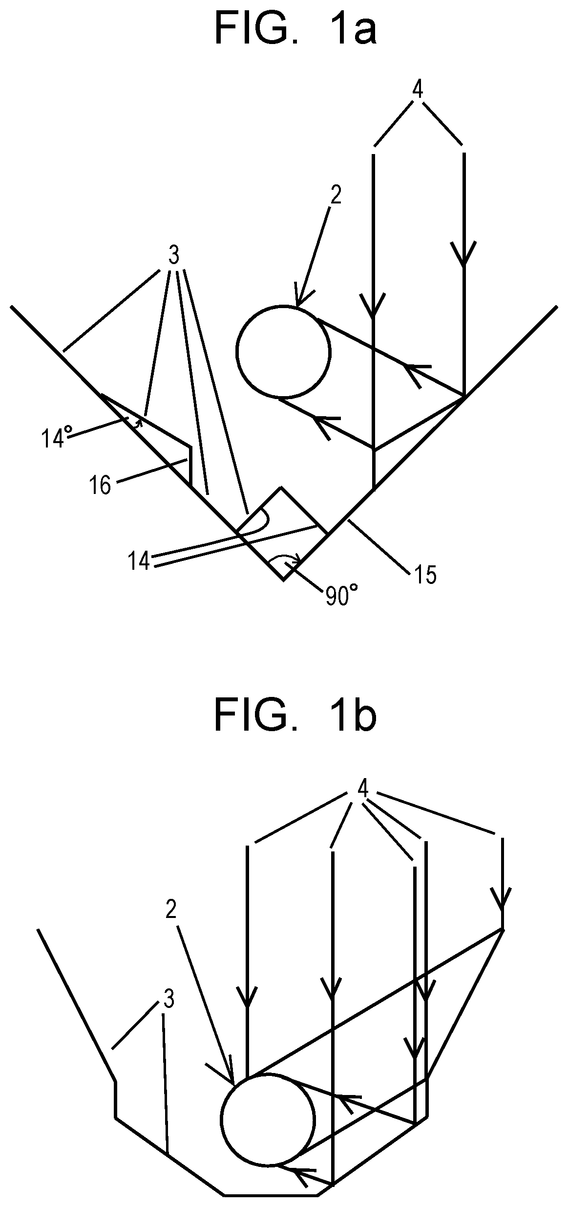
[0018]FIGS. 1a and 1b are cross-sectional representations of the basic concept of the present invention designed to illustrate the theory and operation of the invention.

[0019]Referring in detail to FIG. 1a, the V shape of the underlying support structure, i.e., the trough 15, is illustrated by the flat, i.e, planar, surfaces. Because each side of the trough 15 is planar, it can be sourced from off-the-shelf materials which will allow for reduction of costs compared to other trough designs that require a support structure adapted to accommodate curved mirrors or a curved underlying geometry. Additionally, the trough 15 is preferably constructed in a lattice-type configuration, which provides a number of benefits, including, but not limited to, weight and cost reduction, modularity, and hence, portability and eas...


PUM

PropertyMeasurementUnit
angleaaaaaaaaaa
solar radiationaaaaaaaaaa
widthaaaaaaaaaa

Abstract

The present invention is a solar concentrator composed of a generally V-shaped trough of reflective Fresnel steps. The reflective Fresnel steps concentrate the sunlight entering the mouth of the V-shaped trough and parallel to its central axis into a central focal area. By disposing a solar energy receiving element at the central focal area of sunlight concentration, a concentrating solar energy collector is created. Various configurations of solar energy receiving elements are used to convert the concentrated sunlight into other forms of useful energy that can be harvested by the collector.

Description

CROSS-REFERENCE TO RELATED APPLICATION(S)[0001]The present application is a continuation-in-part of, and claims priority to, U.S. Non-provisional application Ser. No. 15 / 909,850 filed on Mar. 1, 2018, entitled “TROUGH SHAPED FRESNEL REFLECTOR SOLAR CONCENTRATOR”, which application is a continuation-in-part of, and claims priority to, U.S. Non-provisional application Ser. No. 14 / 162,320 filed on Jan. 23, 2014, entitled “COMPOUND LINEAR V FRESNEL-PARABOLIC TROUGH SOLAR CONCENTRATOR”, which application is a continuation-in-part of, and claims priority to, U.S. Non-provisional application Ser. No. 13 / 337,206 filed on Dec. 26, 2011, entitled “TROUGH SHAPED FRESNEL REFLECTOR SOLAR CONCENTRATOR”, which application claims benefit of U.S. Provisional Application No. 61 / 427,433 filed on Dec. 27, 2010, entitled “TROUGH SHAPED FRESNEL REFLECTOR SOLAR CONCENTRATOR”, the entire disclosures of which are incorporated by reference herein.BACKGROUND OF THE INVENTION1. Field of Invention[0002]The pres...

Claims


Application Information

Patent Timeline
Patent Type & Authority Applications(United States)
IPC IPC(8): H02S40/22F24S23/70F24S10/70F24S30/42H02S20/32H02S40/44G02B19/00G02B5/09
CPCF24S30/42F24S10/70G02B5/09G02B19/0019F24S2023/872F24S2010/71G02B19/0042F24S23/80H02S40/44H02S40/22H02S20/32H01L31/0521H01L31/0547Y02E10/44Y02E10/47Y02E10/52Y02E10/60
Inventor CITRON, JEFFREY MICHAEL
Owner CITRON JEFFREY MICHAEL
Why Eureka
Try Eureka