

Method and apparatus for monitoring capacitor faults in a capacitor bank
Patent Information
- Authority / Receiving Office
- US · United States
- Current Assignee / Owner
- GENTEC
- Publication Date
- 2020-07-30
Smart Images
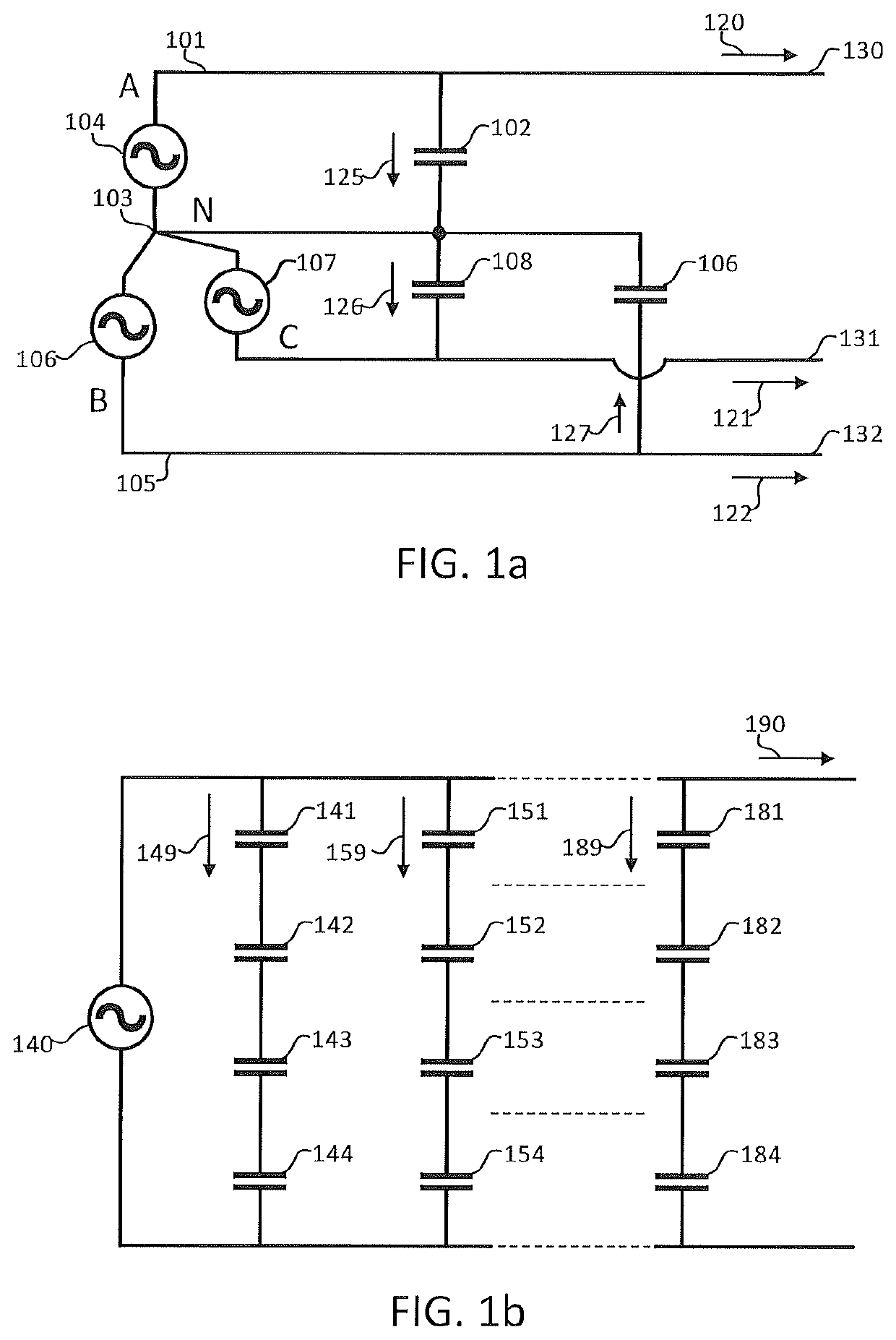
Figure 1 
Figure 2 
Figure 3
Abstract
Description
FIELD
[0001] The invention relates to a digital protection relay for protecting power systems. More precisely, one or more embodiments of the invention pertain to a method and an apparatus for monitoring capacitor faults in a capacitor bank connected to an AC system.BACKGROUND
[0002] Protecting the three-phase electrical grid and related equipment from unplanned device short-circuit is very desirable.
[0003] Transport and distribution lines of the electrical grid are inductive in nature and they connect to a load that is also inductive in nature. Therefore, capacitor banks are required for supplying the reactive power absorbed by the connected lines and loads.
[0004] These capacitor banks are distributed throughout the electrical network and operate at various voltage levels, as known to the skilled addressee.
[0005] In many cases, high voltage capacitor banks are formed by connecting multiple capacitor elements in series to form a capacitor string and by paralleling a certain number of such ...