Brightness and contrast optimization of images in real time

a technology of brightness and contrast optimization and image, applied in the field of recording images, can solve the problems of inability to apply the above-mentioned optimization methods, all these technologies are not usually present, and algorithms and methods require considerable computing resources in order to process images in real time, so as to maximize the brightness of the block, maximize the brightness, and optimize the effect of contras

Active Publication Date: 2020-07-30
ROBERT BOSCH GMBH
View PDF0 Cites 0 Cited by
  • Summary
  • Abstract
  • Description
  • Claims
  • Application Information

AI Technical Summary

Benefits of technology

[0012]It is advantageously also provided that a scaling factor is determined as a processing parameter for each block of the auxiliary map. The maximum brightness value of the block is to be scaled using the scaling factor, in order to achieve a maximum brightness value, which is representable by one pixel. The brightness of the block is thus maximized. At the same time, it is ensured that no saturation occurs, as a result of which pieces of image information would be lost. It is therefore ensured by the choice of the scaling factor that even the brightest pixels still remain beyond saturation. The dimmer pixels are thus maximally brightened by the scaling factor.
[0013]An offset value and a multiplier are advantageously also to be ascertained as processing parameters for each block. The offset value is ascertained, in particular, on the basis of a minimal brightness value of the pixels of the block. The multiplier is preferably ascertained based on the distribution of the brightness values of the pixels of the block. In this way, the brightness values of the pixels of each block may be extended between a maximum brightness value and a minimum brightness value after subtraction of the offset value and subsequent multiplication by the multiplier. The maximum brightness value and the minimum brightness value are extreme values that are representable by the pixel. This means that a contrast is optimized. A maximum value range, which is implementable by one pixel is, in particular, utilized to the extent possible. This means that darker pixels are maximally darkened, whereas brighter pixels are maximally brightened. At the same time, it is ensured that no saturation occurs, so that no loss of information of any kind is present. It is also ensured that individual pixel values are not lost, this means that a lowering to mathematically below zero does not take place. Thus, it is ensured, in turn, that no loss of information occurs.
[0014]A predefined tolerance range is preferably disregarded in the above-described maximum brightness values and / or minimum brightness values that are representable by one pixel. This means that the maximum value that a pixel may assume is not considered to be the maximum brightness value of a pixel, but a value, which is calculated from the theoretically maximum possible value minus the tolerance range. The same applies for the minimum brightness value, which is calculated from the minimum value, in particular, from the value zero, plus the tolerance range. In this way, it may be ensured that during a further processing, in particular, during the application of the processing function after interpolation of the processing parameters, each processed pixel remains safely and reliably within the representable range. Thus, no saturation occurs, as a result of which the risk of a loss of information is reduced.

Problems solved by technology

However, all these algorithms and methods require considerable computing resources in order to process images in real time.
However, all these technologies are not usually present in control units.
Thus, an application of the aforementioned optimization methods is not possible.
By scaling down, there is the risk of introducing inaccuracies into the auxiliary map.
In the second case, there is the risk of an image noise occurring.

Method used


Image

  • Brightness and contrast optimization of images in real time
  • Brightness and contrast optimization of images in real time
  • Brightness and contrast optimization of images in real time

Examples


Embodiment Construction

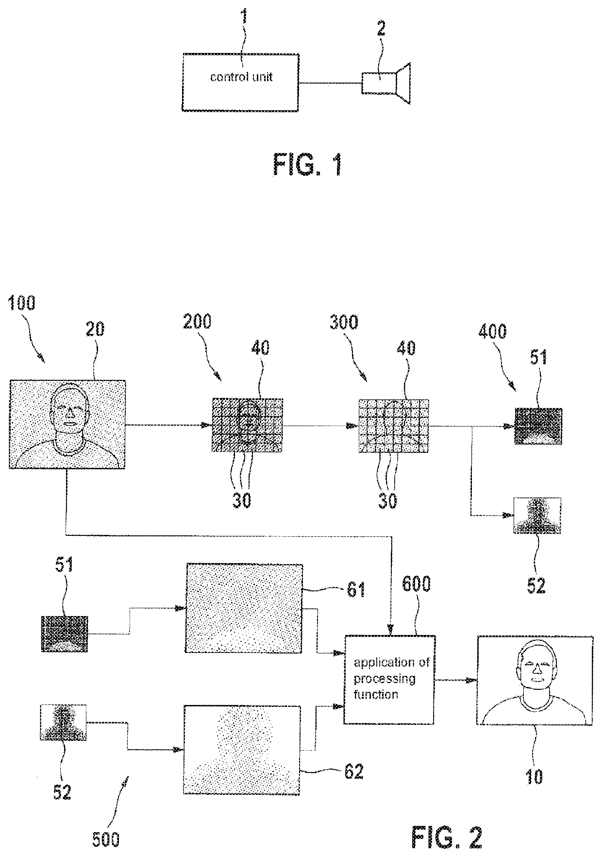
[0030]FIG. 1 schematically shows an example system for carrying out an example method according to one exemplary embodiment of the present invention. The system includes a control unit 1 and a sensor 2. The method described below is preferably implementable on control unit 1. The method is used to record and optimize images in real time. A sequence map of the method is schematically depicted in FIG. 2.

[0031]An area of the surroundings is initially detected 100 using sensor 2. In the process, a map 20 is produced, which has a predefined number of pixels, each of which indicates brightness values. Each pixel carries, in particular, an 8 bit value, which represents the aforementioned brightness. For example, the map 20 may have a resolution of 752×640 pixels.

[0032]Map 20 is subdivided into blocks 30 having a predefined first size. The predefined first size corresponds, in particular, to a size that includes individual image features, which are to remain present in any case, even after ...


PUM


Abstract

A method for recording an image. The method includes: detecting an area using a sensor and generating a map of the area having a predefined number of pixels, which indicate brightness values, and subdividing the map into blocks) having a predefined first size, creating an auxiliary map by scaling down the blocks to a predefined second size, which is smaller than the predefined first size, sorting the pixels of each block of the auxiliary map according to their brightness values, determining processing parameters for each block on the basis of the sorted pixels, with which the pixels of the associated block are processed in order to achieve a brightness maximization and/or a contrast maximization, interpolating a processing function from the processing parameters, and applying the processing function to the pixels of the map to generate the image.

Description

FIELD[0001]The present invention relates to a method for recording an image. An optimization of brightness and / or contrast of the image take / takes place, in particular, in real time. The present invention further relates to a computer program and a control unit for carrying out the method.BACKGROUND INFORMATION[0002]Various algorithms are described in the related art for optimizing images. Thus, for example, the AINDANE algorithm is described in the following document: “Li Tao and Vijayan K. Asari: Adaptive and integrated neighborhood-dependent approach for non-linear enhancement of colour images, Journal of Electronic Imaging 14(4):043006—October 2005.”[0003]The SCRCLCE method is described in the following document: “Tsai, C. & Chou, C. J Image Video Proc. (2011)2011:6. doi:10.1186 / 1687-5281-2011-6.”[0004]However, all these algorithms and methods require considerable computing resources in order to process images in real time. Thus, correspondingly rapidly clocked CPUs (central pro...

Claims


Application Information

Patent Timeline
Patent Type & Authority Applications(United States)
IPC IPC(8): G06T5/00G06T5/40G06T5/50G06T3/40
CPCG06T5/009G06T5/50G06T3/4015G06T5/40G06T5/008H04N1/4072H04N5/20H04N5/57G06T2207/20016G06T2207/20021H04N23/80H04N23/71H04N5/067
Inventor GYURASZ, GABOR
Owner ROBERT BOSCH GMBH
Why Eureka
Try Eureka