
Plasma display panel comprising single barrier ribs and double barrier ribs

Inactive Publication Date: 2008-07-17
SAMSUNG SDI CO LTD
View PDF3 Cites 0 Cited by
  • Summary
  • Abstract
  • Description
  • Claims
  • Application Information

AI Technical Summary

Benefits of technology

[0008]The present embodiments provide a plasma display panel capable of maximizing brightness by improving both 1% peak brightness and full white brightness and of minimizing power consumption.
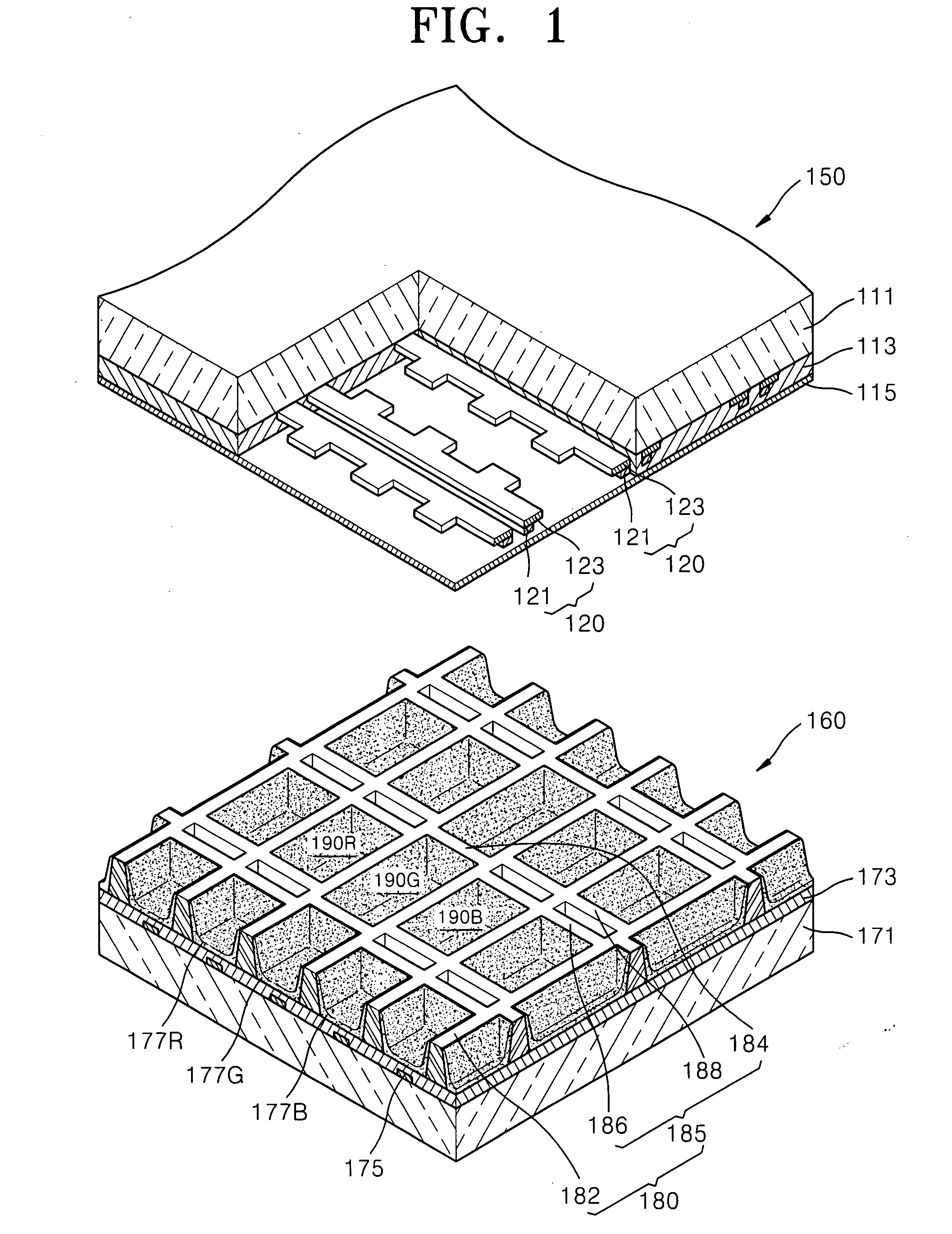
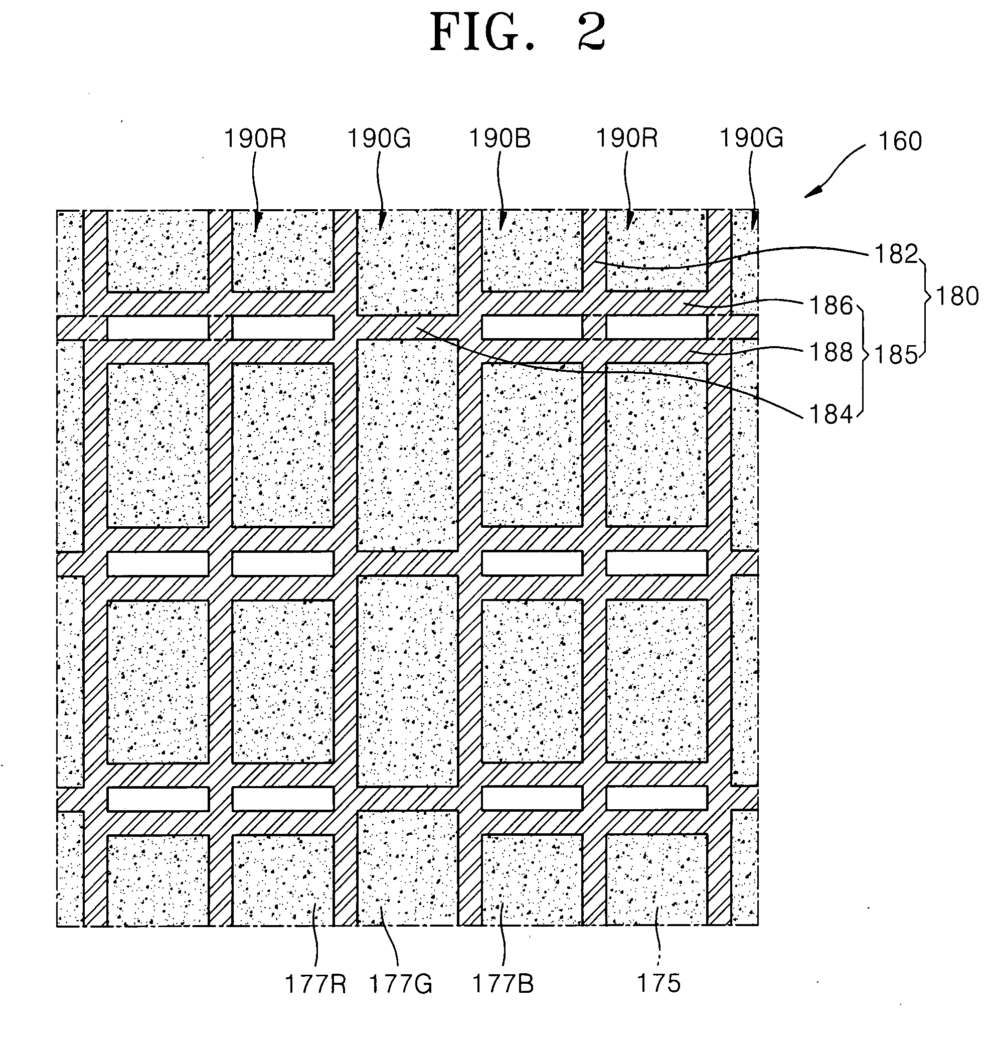
[0012]The discharge cells may include first discharge cells and second discharge cells that have higher brightness than the first discharge cells. The first discharge cells may be defined by the double barrier ribs, and the second discharge cells may be defined by the single barrier ribs, so that the second discharge cells having higher brightness are wider than the first discharge cells having lower brightness. Thus, the brightness of the plasma display panel is increased.
[0014]The discharge electrodes may include transparent electrodes and bus electrodes. The bus electrodes are arranged over the double barrier ribs, such that the aperture ratio of the plasma display panel can be increased.
[0017]The discharge electrodes include X electrodes and Y electrodes to which voltages are alternately applied. The X electrodes includes X transparent electrodes and X bus electrodes. The Y electrodes include Y transparent electrodes and Y bus electrodes. The Y electrodes can apply different voltages to the discharge cells, whereas the X electrodes can apply a common voltage to the discharges. Accordingly, the X electrodes may be integrally formed, and may be arranged over the double barrier ribs and single barrier ribs of the horizontal ribs in order to improve the aperture ratio of the plasma display panel.

Problems solved by technology

More specifically, the greater the full white brightness is, the smaller the power consumption is.

Method used


Image

  • Plasma display panel comprising single barrier ribs and double barrier ribs
  • Plasma display panel comprising single barrier ribs and double barrier ribs
  • Plasma display panel comprising single barrier ribs and double barrier ribs

Examples


Embodiment Construction

[0031]The present embodiments will now be described more fully with reference to the accompanying drawings, in which exemplary embodiments are shown.

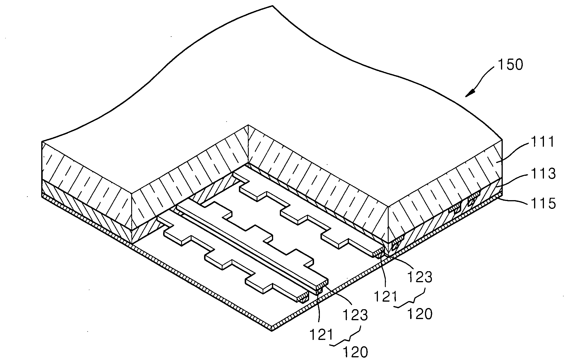
[0032]FIG. 1 is an exploded perspective view of a plasma display panel according to an embodiment. FIG. 2 is a plan view of a bottom panel 160 of the plasma display panel shown in FIG. 1.

[0033]Referring to FIG. 1, the plasma display panel includes an upper panel 150 and a lower panel 160.

[0034]The upper panel 150 includes an upper substrate 111, a plurality of discharge electrodes 120 arranged parallel to one another on the upper substrate 111, and an upper dielectric layer 113 formed on the upper substrate 111 and covering the discharge electrodes 120. A protection layer 115 is formed on the upper dielectric layer 113.

[0035]The upper substrate 111 may be formed of a highly optical transmissive material, such as glass, as a main component.

[0036]The discharge electrodes 120 include wide transparent electrodes 123 that transmit light, and...


PUM


Abstract

A plasma display panel capable of minimizing power consumption and maximizing a brightness is provided. The plasma display panel includes a front substrate and a rear substrate arranged to face each other, a plurality of horizontal ribs defining a discharge space between the front and rear substrates, the horizontal ribs comprising single barrier ribs and double barrier ribs, a plurality of vertical ribs arranged perpendicularly to the horizontal ribs to define the discharge space into a plurality of discharge cells, and a plurality of pairs of discharge electrodes to which a voltage is applied so that a discharge is generated within the discharge cells.

Description

CROSS-REFERENCE TO RELATED PATENT APPLICATION[0001]This application claims the benefit of Korean Patent Application No. 10-2007-0005444, filed on Jan. 17, 2007, in the Korean Intellectual Property Office, the disclosure of which is incorporated herein in its entirety by reference.BACKGROUND OF THE INVENTION[0002]1. Field of the Invention[0003]The present embodiments relate to a plasma display panel including single barrier ribs and double barrier ribs.[0004]2. Description of the Related Art[0005]In general plasma display panels, barrier ribs are arranged between a front panel and a rear panel define a plurality of discharge cells. Also, a phosphor material is coated on the barrier ribs and each of the discharge cells is filled with a main discharge gas, such as Ne, He, or a mixture of Ne and He, and an inert gas including a small amount of xenon (Xe). Such plasma display panels display images by applying a high frequency voltage to the discharge cells to generate vacuum ultraviolet ...

Claims


Application Information

Patent Timeline
IPC IPC(8): H01J17/49
CPCH01J11/12H01J11/36H01J2211/38H01J2211/365H01J2211/245H01J11/38H01J2211/361H01J2211/363
Inventor SONG, JUNG-SUK
Owner SAMSUNG SDI CO LTD
Learn More