High brightness electron impact ion source

a technology of electron impact and electron beam, which is applied in the direction of ion beam tubes, electrical devices, electric discharge tubes, etc., can solve the problem of practicable upper limit of beam intensity, and achieve the effect of substantial brightness of extracted ion beam, maximizing brightness, and reducing linear dimensions correspondingly

Inactive Publication Date: 2017-03-28
NONSEQUITUR TECH INC
View PDF2 Cites 0 Cited by
  • Summary
  • Abstract
  • Description
  • Claims
  • Application Information

AI Technical Summary

Benefits of technology

[0007]According to the invention, an electron impact ion beam source is provided with a pressure chamber to confine a specific high pressure area within excited gas to a small enough volume that the source can be operated at relatively high pressure and still achieve substantial brightness of the extracted ion beam. In particular, the area is configured such that the overall linear dimension along the beam path is less than the mean free path of the ions and the electrons within the chamber. If pressure is increased, the linear dimension must be correspondingly decreased to maximized brightness. By keeping linear dimensions sufficiently small, both incident electrons and extracted ions are enabled to transit the source region without significant energy loss. The new source design allows operation at optimal pressures at least an order of magnitude higher than other known ion sources and thus produces an order of magnitude higher brightness.

Problems solved by technology

As a consequence of the resultant limit on the mean free path of the ions, there is a practical upper limit on beam intensity.

Method used


Image

  • High brightness electron impact ion source
  • High brightness electron impact ion source
  • High brightness electron impact ion source

Examples


Embodiment Construction

[0015]This invention description assumes familiarity with ion beam device structures of the prior art in which an electron beam is directed into a chamber containing a material to be ionized and wherein the extract ions are focused by a focusing column (not shown) on a target (not shown). In this disclosure, the target material to be ionized is preferably a gas such as argon or hydrogen, or any suitable gas that meets the criteria for the particular application. These particular elements have advantages in certain applications in that they leave no material residue on the target. At least the following materials are suitable as ion sources: hydrogen, deuterium, tritium, helium, nitrogen, oxygen, neon, argon, xenon, sulfur hexafluoride, carbon dioxide, and the halogen gases, such as chlorine and fluorine. The invention is not limited by the ion source material.

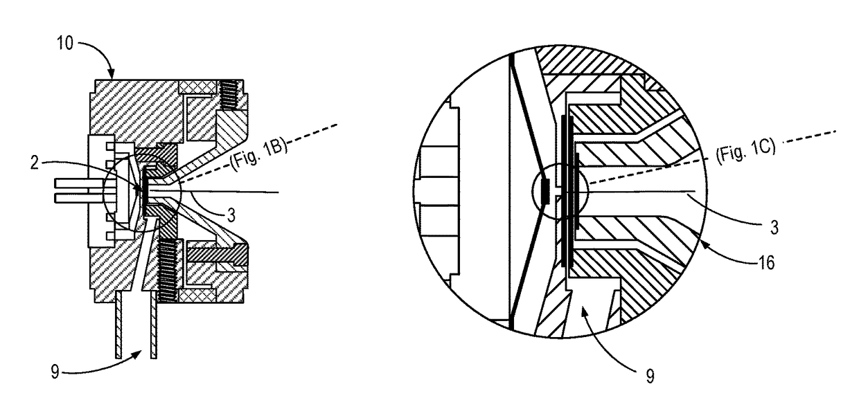
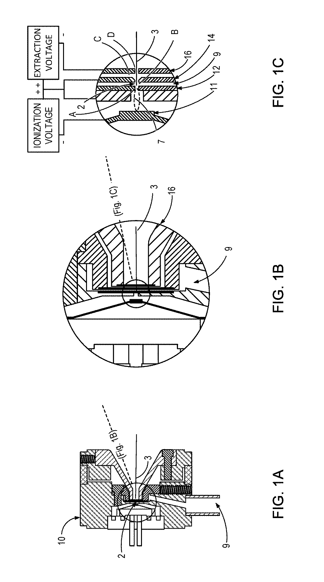
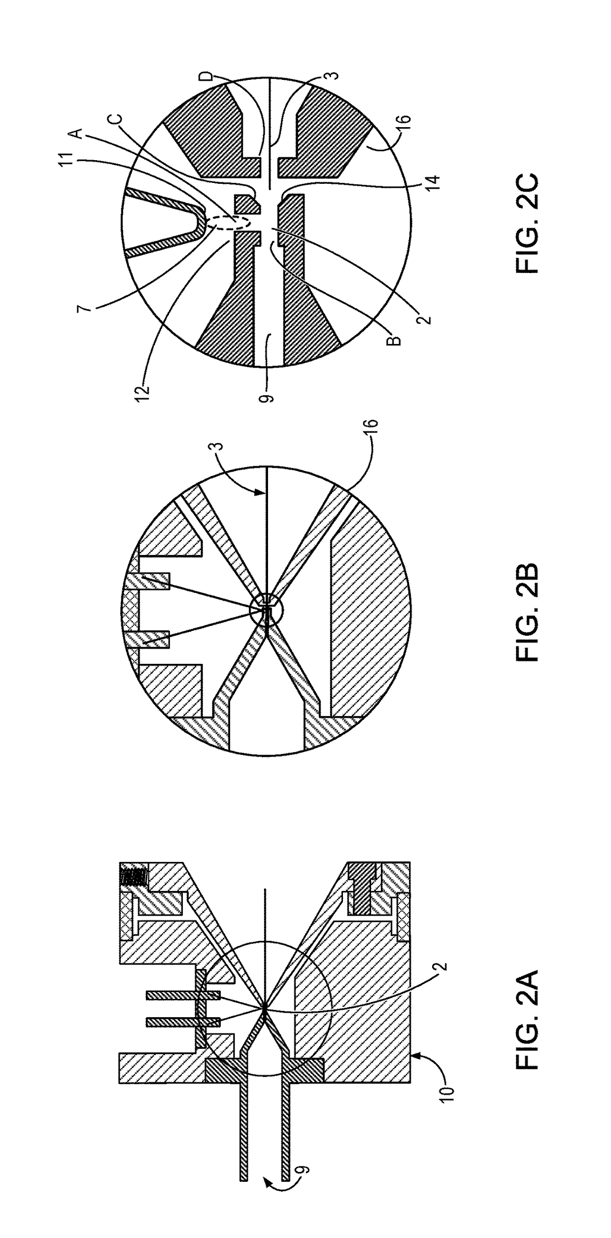
[0016]Referring to FIGS. 1A, 1B and 1C, wherein gas inlet is lateral to the ion beam 3, and to FIGS. 2A, 2B and 2C, wherein g...


PUM


Abstract

An electron impact ion beam source is provided with a pressure chamber to confine a specific high pressure area within excited gas to a small enough volume that the source can be operated at relatively high pressure and still achieve substantial brightness of the extracted ion beam. In particular, the area is configured such that the overall linear dimension along the beam path is less than the mean free path of the ions and the electrons within the chamber. If pressure is increased, the linear dimension must be correspondingly decreased to maximized brightness. By keeping linear dimensions sufficiently small, both incident electrons and extracted ions are enabled to transit the source region without significant energy loss. The new source design allows operation at pressures at least an order of magnitude higher than other known ion sources and thus produces an order of magnitude higher brightness.

Description

CROSS-REFERENCES TO RELATED APPLICATIONS[0001]Not ApplicableSTATEMENT AS TO RIGHTS TO INVENTIONS MADE UNDER FEDERALLY SPONSORED RESEARCH AND DEVELOPMENT[0002]Not ApplicableREFERENCE TO A “SEQUENCE LISTING,” A TABLE, OR A COMPUTER PROGRAM LISTING APPENDIX SUBMITTED ON A COMPACT DISK[0003]Not ApplicableBACKGROUND OF THE INVENTION[0004]This invention relates to ion source devices and in particular to a high brightness electron impact gas phase ion source device for use in connection with a focusing column.[0005]In order to produce a small intense focused ion beam spot, it is preferred to start with the brightest possible ion source. One way to increase the brightness in a gas phase ion source is to increase the plasma density in the source. In an electron impact source, increasing the gas pressure will increase the plasma density. At some gas pressure, depending upon the geometry of the source, the mean free path of both the electrons used to ionize the gas and the ions being extracted...

Claims


Application Information

Patent Timeline
Patent Type & Authority Patents(United States)
IPC IPC(8): H01J27/00H01J27/20H01J27/02
CPCH01J27/205H01J27/022
Inventor LOEFFLER, PETER E.
Owner NONSEQUITUR TECH INC
Why Eureka
Try Eureka