Electric motor with improved heat dissipation and productivity and method for manufacturing same

Active Publication Date: 2020-07-30
FANUC LTD
View PDF0 Cites 1 Cited by
  • Summary
  • Abstract
  • Description
  • Claims
  • Application Information

AI Technical Summary

Benefits of technology

The patent is looking for a simple way to improve the heat dissipation and productivity of an electric motor.

Problems solved by technology

Further, because a dedicated mold, an injection molding machine, and the like are required, there is the problem that manufacturing costs increase.
On the other hand, techniques relying solely on a winding impregnating agent cause a reduction in rated torque due to insufficient heat dissipation.

Method used


Image

  • Electric motor with improved heat dissipation and productivity and method for manufacturing same
  • Electric motor with improved heat dissipation and productivity and method for manufacturing same
  • Electric motor with improved heat dissipation and productivity and method for manufacturing same

Examples


Embodiment Construction

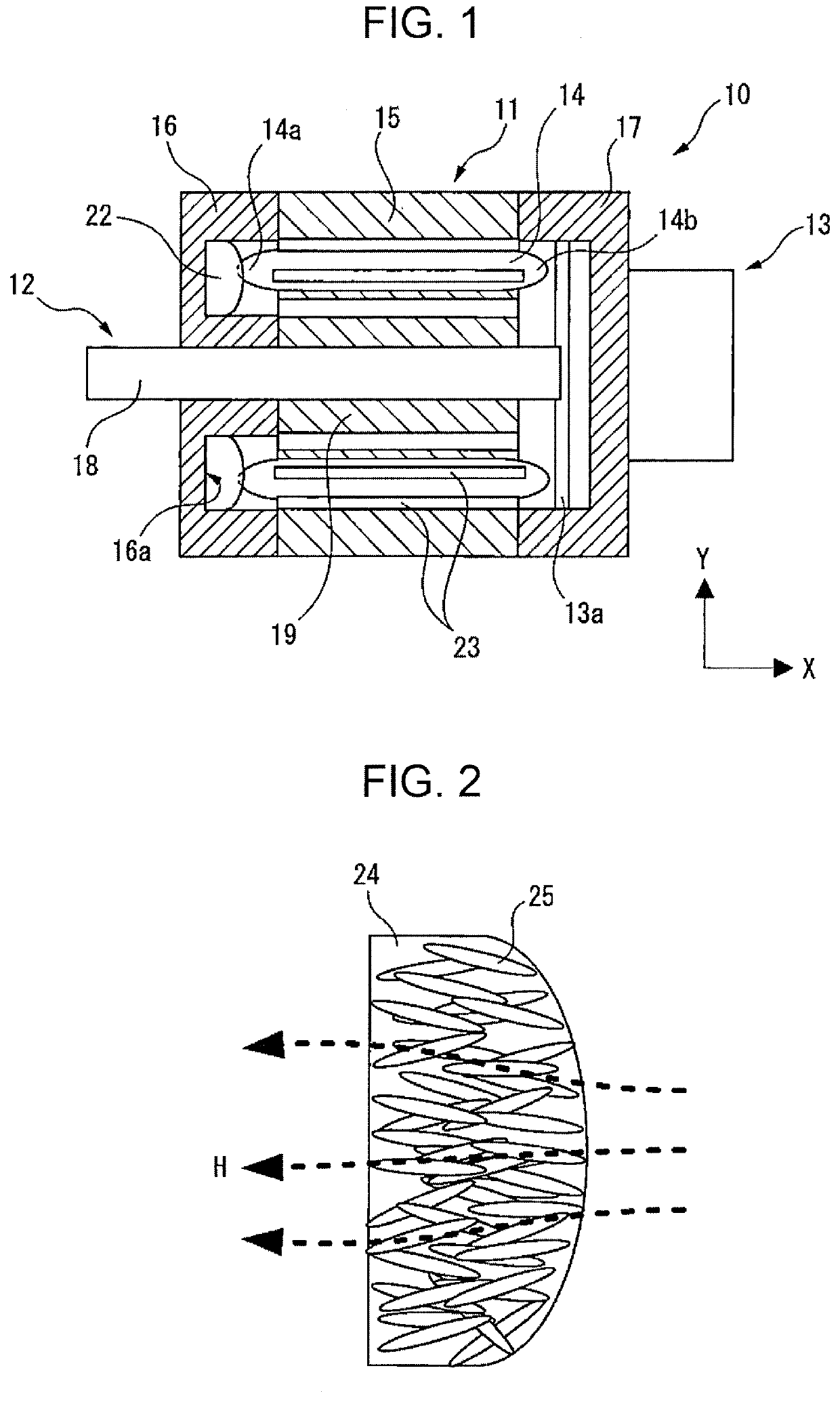
[0030]Embodiments of the present disclosure will be described below with reference to the accompanying drawings. In the drawings, identical or similar constituent elements are given identical or similar reference signs. Additionally, the embodiments described below are not intended to limit the technical scope of the disclosure or the meaning of terms set forth in the claims. Note that, in this specification, the terms “front” or “forward” refer to a load side and an output side of an electric motor, and the terms “rear” or “rearward” refer to the side opposite to the load side and the side opposite to the output side of the electric motor.

[0031]FIG. 1 is a cross-sectional view of an electric motor 10 in the present embodiment. Note that while the electric motor 10 of the present example is, for example, a servo motor, other electric motors can be used as long as the electric motor includes a winding in the stator. The electric motor 10 includes a stator 11, a rotor 12 disposed on a...


PUM


Abstract

An electric motor includes a front housing positioned on a load side and including an annular groove in an inner surface of the front housing, a winding wound around a stator core and including a coil end projecting forward from the stator core and disposed in the annular groove, and a heat conductive resin filled in the annular groove and configured to be in contact with both the coil end and the front housing.

Description

BACKGROUND OF THE INVENTION1. Field of the Invention[0001]The present invention relates to an electric motor and a method for manufacturing the electric motor, and particularly relates to an electric motor with improved heat dissipation and productivity, and a method for manufacturing the electric motor.2. Description of the Related Art[0002]A rise in temperature of a winding caused by heat build-up is directly linked to a decrease in a continuous rated torque of an electric motor. Releasing the heat of the winding to the outside is therefore an important issue. Known techniques for improving the heat dissipation and the like of the winding include, for example, a resin mold type in which the entire winding is covered with resin, and a technique that relies solely on a winding impregnating agent that fills a gap between the winding and the stator core.[0003]FIG. 8 is a schematic diagram illustrating an example of an electric motor 50 having increased heat dissipation by a molded res...

Claims


Application Information

Patent Timeline
IPC IPC(8): H02K9/22H02K5/08H02K15/12H02K15/14
CPCH02K15/12H02K5/08H02K15/14H02K9/22H02K1/16H02K1/20H02K15/02H02K9/223H02K9/227
Inventor ARAI, LEO
Owner FANUC LTD
Why Eureka
Try Eureka