Vehicle

a technology for vehicles and batteries, applied in the field of vehicles, can solve the problems of reducing the distance between affecting the performance of the battery, so as to achieve the effect of ensuring the distance between the ground and the battery and reducing the distance between the battery and the floor panel

Active Publication Date: 2020-08-06
HONDA MOTOR CO LTD
View PDF0 Cites 15 Cited by
  • Summary
  • Abstract
  • Description
  • Claims
  • Application Information

AI Technical Summary

Benefits of technology

[0016]According to the above embodiment of the present invention, a first cooling pipe and a second cooling pipe that connect a cooling device provided in a front room and an electric motor control device provided in a rear side of a vehicle interior are accommodated in a recessed portion of a floor panel, so that the distance between a battery and the floor panel can be reduced, and the distance between the ground and the battery can be ensured.

Problems solved by technology

In this case, a cooling pipe connecting the cooling device and the motor control device needs to be arranged from a front part of the vehicle to the rear part of the vehicle, but if the cooling pipe is arranged on the side to avoid the battery, the cooling pipe may be damaged due to foreign matters or impact from the outside.
Further, if the cooling pipe is arranged between the battery and the floor panel, there is a risk that an installation height of the battery is lowered due to the influence of the cooling pipe, and the distance between the ground and the battery may be reduced.

Method used


Image

  • Vehicle
  • Vehicle
  • Vehicle

Examples


first embodiment

[0028][Overall Structure of Vehicle]

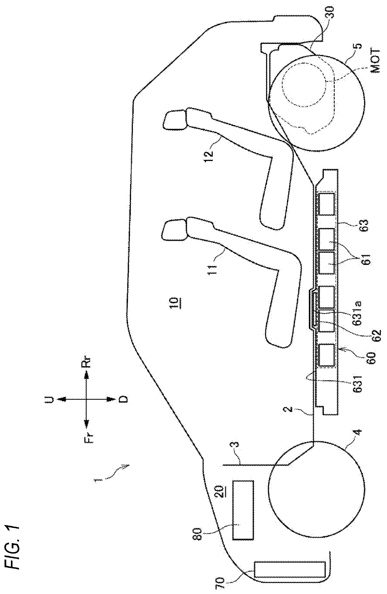
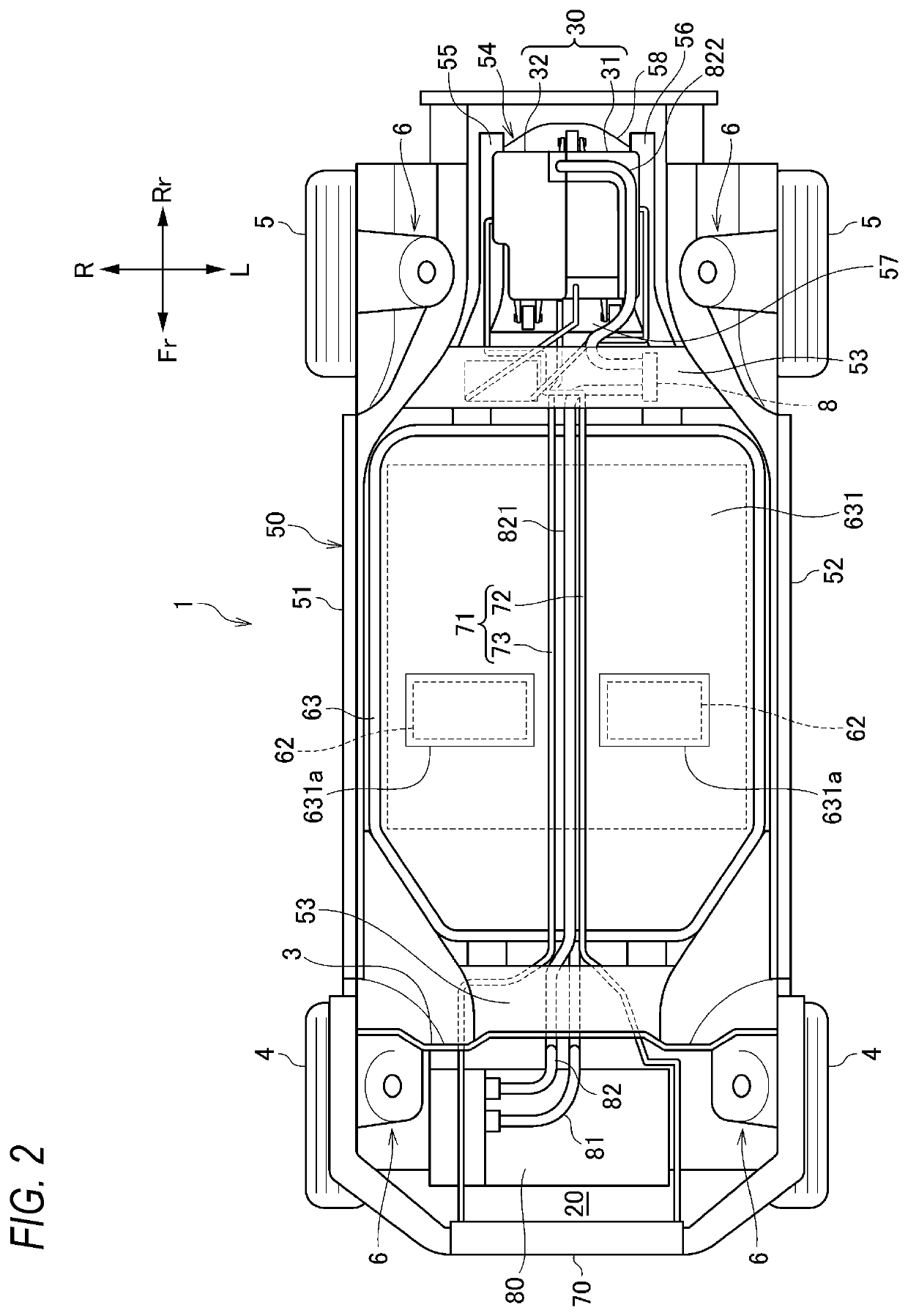
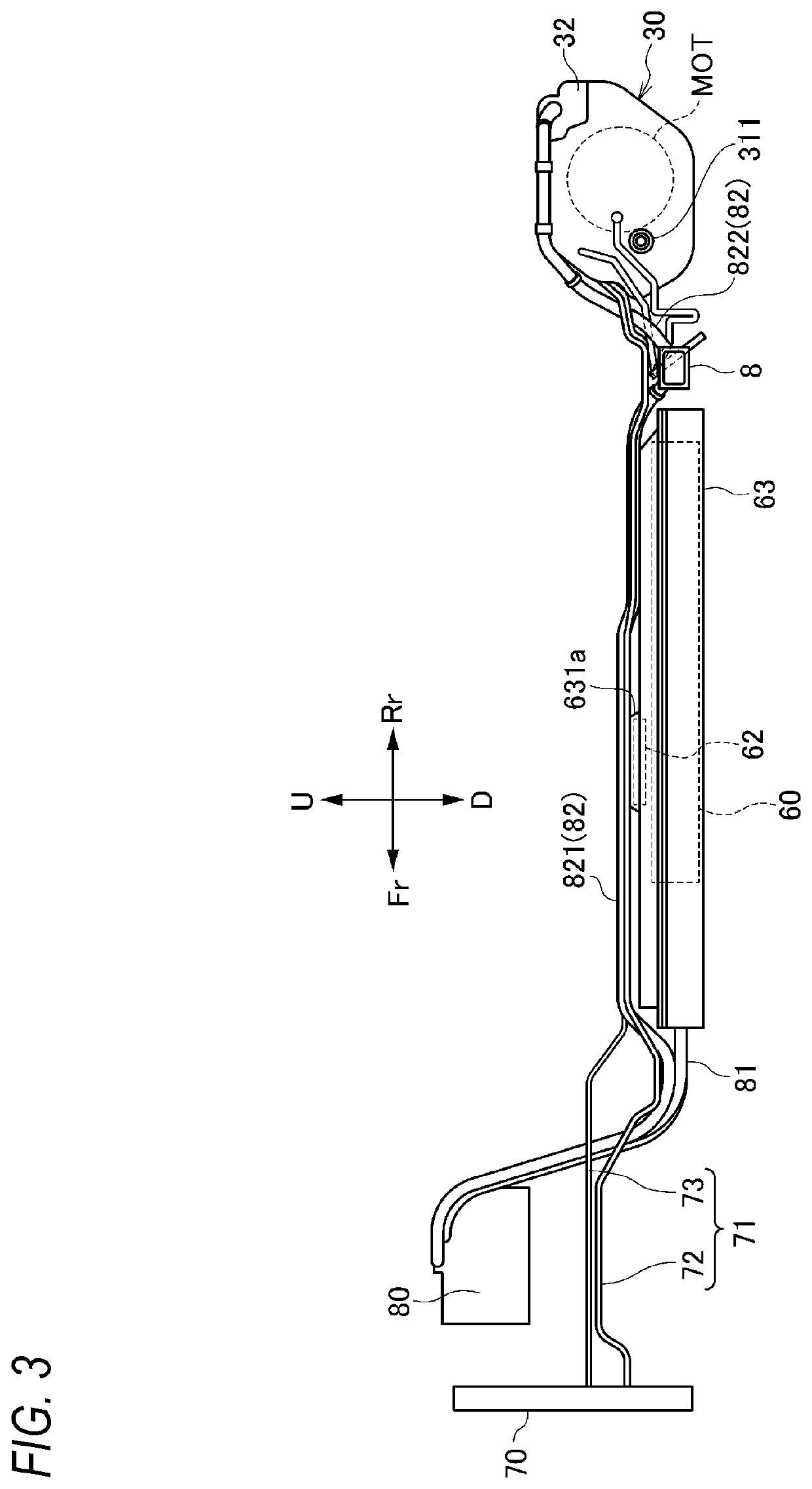
[0029]As shown in FIGS. 1 and 2, a vehicle 1 according to a first embodiment of the present invention is formed by a vehicle interior 10 and a front room 20 in front of the vehicle interior 10, which are defined by a floor panel 2 and a dash panel 3. Front seats 11 and rear seats 12 are provided in the vehicle interior 10. A driving device unit 30 is provided below the floor panel 2 in rear of the rear seats 12. The driving device unit 30 drives left and right rear wheels 5. That is, in the vehicle 1, the left and right rear wheels 5 are driving wheels, and left and right front wheels 4 are driven wheels. The front wheels 4 and the rear wheels 5 are supported by a vehicle body frame 50 via suspensions (not shown) supported by respective suspension support portions 6.

[0030][Vehicle Body Frame]

[0031]A vehicle body frame 50 includes a pair of left and right side members 51, 52 extending in a front-rear direction, a plurality of cross members 53 exten...

second embodiment

[0054]Next, a second embodiment will be described with reference to FIGS. 8 to 10. Note that the description of the first embodiment is incorporated by denoting the same configurations as those of the first embodiment with the same reference numerals as in the first embodiment.

[0055]The vehicle 1 of the second embodiment further includes an inverter 90 provided in the rear of the vehicle interior 10 and above the floor panel 2. The inverter 90 is a power conversion device for supplying AC100V power to an AC100V outlet (not shown) provided in the vehicle interior 10, and is connected to the battery 60 via an inverter cable 91. The inverter cable 91 extending from the inverter 90 passes through the floor panel 2 and is disposed in the recessed portion 2a. More specifically, the inverter cable 91 is fixed to a plurality of bridge members 74 that connect the first cooling pipe 72 and the second cooling pipe 73 so as to be parallel to the PCU cable 82, and is accommodated in the recessed...


PUM


Abstract

A vehicle includes a vehicle interior; a front room provided in front of the vehicle interior; an electric motor control device provided at a rear side of the vehicle interior and below a floor panel; a battery provided below the vehicle interior and below the floor panel; a cooling device provided in the front room; a first cooling pipe configured to supply a refrigerant from the cooling device to the electric motor control device; and a second cooling pipe configured to discharge the refrigerant from the electric motor control device to the cooling device. The floor panel has a recessed portion recessed upwards, and the first cooling pipe and the second cooling pipe are accommodated in the recessed portion.

Description

CROSS-REFERENCE TO RELATED APPLICATIONS[0001]This application is based on and claims priority under 35 USC 119 from Japanese Patent Application No. 2019-017411 filed on Feb. 1, 2019.TECHNICAL FIELD[0002]The present invention relates to a vehicle including an electric motor control device and a cooling device that cools the electric motor control device.BACKGROUND ART[0003]In the vehicle disclosed in JP-A-2018-96280, an electric motor control device (PCU) and a cooling device that cools the electric motor control device (radiator) are arranged in a front room provided in front of a vehicle interior.[0004]In a rear-wheel drive vehicle, an electric motor and an electric motor control device are arranged at a rear part of the vehicle, while a battery is arranged below a floor panel at the center of the vehicle and a cooling device may be arranged in a front room. In this case, a cooling pipe connecting the cooling device and the motor control device needs to be arranged from a front par...

Claims


Application Information

Patent Timeline
Patent Type & Authority Applications(United States)
IPC IPC(8): B60K1/00B60L50/60B60L50/64B60K11/04B60K1/04
CPCB60L50/66B60K2001/0438B60K11/04B60K2001/006B60L50/64B60K1/00B60K1/04B60R11/00B60R16/02B60R2011/0001H05K7/20B60K11/02Y02T10/70
Inventor KOCHI, NAOTOSAKAMOTO, TETSUHISAIZAWA, RYOSAKU
Owner HONDA MOTOR CO LTD
Why Eureka
Try Eureka