Filter circuit, filter circuit element, and multi/demultiplexer
a filter circuit and filter element technology, applied in the field of filter circuits, can solve the problems of increasing insertion loss in the pass frequency band, difficult to achieve impedance matching over a wide band, etc., and achieve the effects of reducing or preventing insertion loss, increasing insertion loss in the stop frequency band, and reducing insertion loss in the pass frequency band
- Summary
- Abstract
- Description
- Claims
- Application Information
AI Technical Summary
Benefits of technology
Problems solved by technology
Method used
Image
Examples
first preferred embodiment
[0051]In a first preferred embodiment of the present invention, an example applied to a low pass filter will be described.
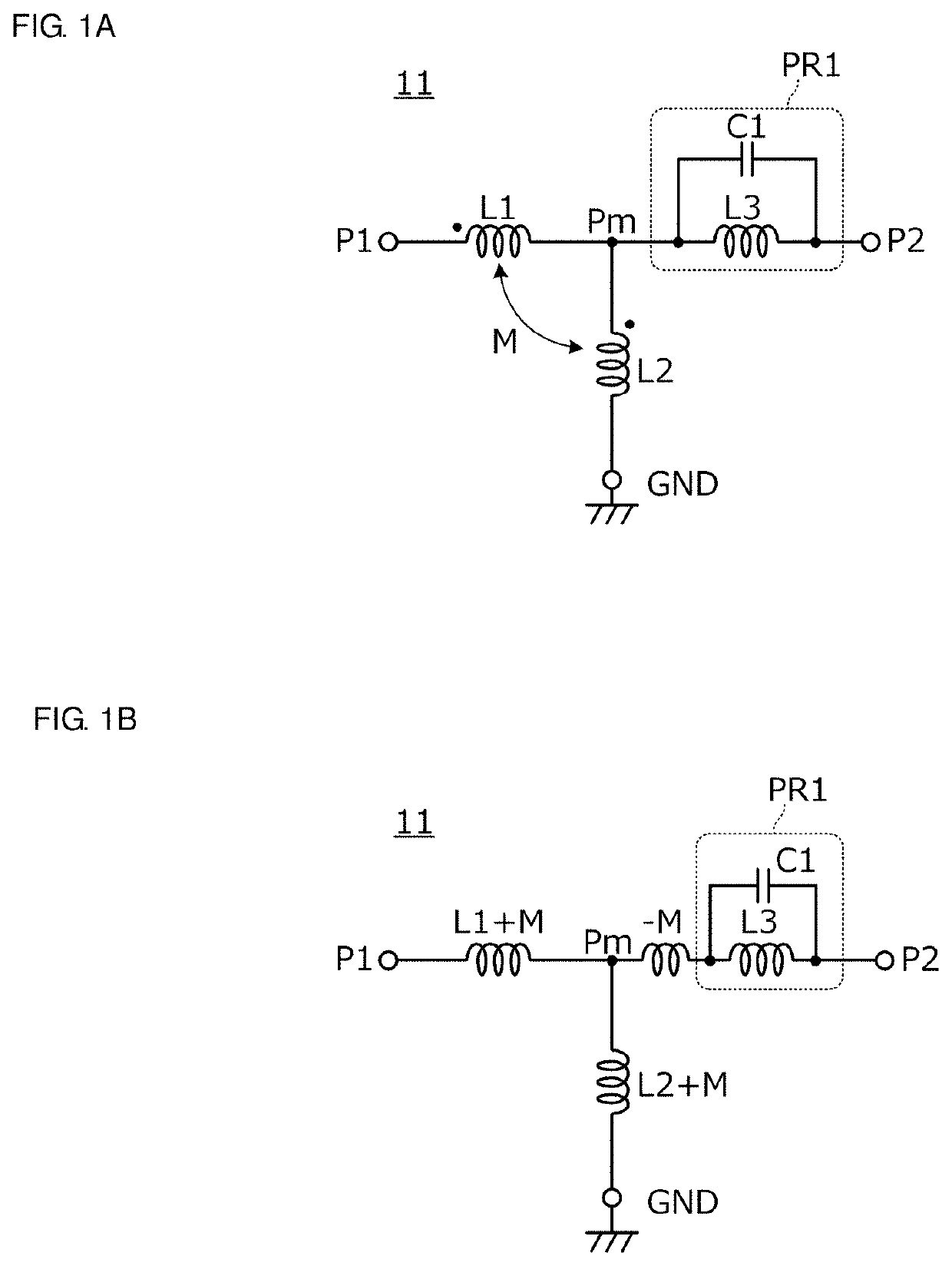
[0052]FIG. 1A is a circuit diagram of a low pass filter 11 according to the first preferred embodiment. FIG. 1B is an equivalent circuit diagram of the low pass filter 11.
[0053]The low pass filter 11 of the first preferred embodiment includes a first port P1, a second port P2, an intermediate node Pm between the first port P1 and the second port P2, and a ground terminal GND. Both the first port P1 and the second port P2 are input / output ports, and one is included in an input port, and the other is included in an output port.
[0054]Further, the low pass filter 11 includes a first inductor L1, a second inductor L2, a third inductor L3, and a first capacitor C1.
[0055]The first inductor L1 is electrically connected between the first port P1 and the intermediate node Pm. The second inductor L2 is electrically connected between the intermediate node Pm and the ground t...
second preferred embodiment
[0063]In a second preferred embodiment of the present invention, also, an example applied to a low pass filter will be described.
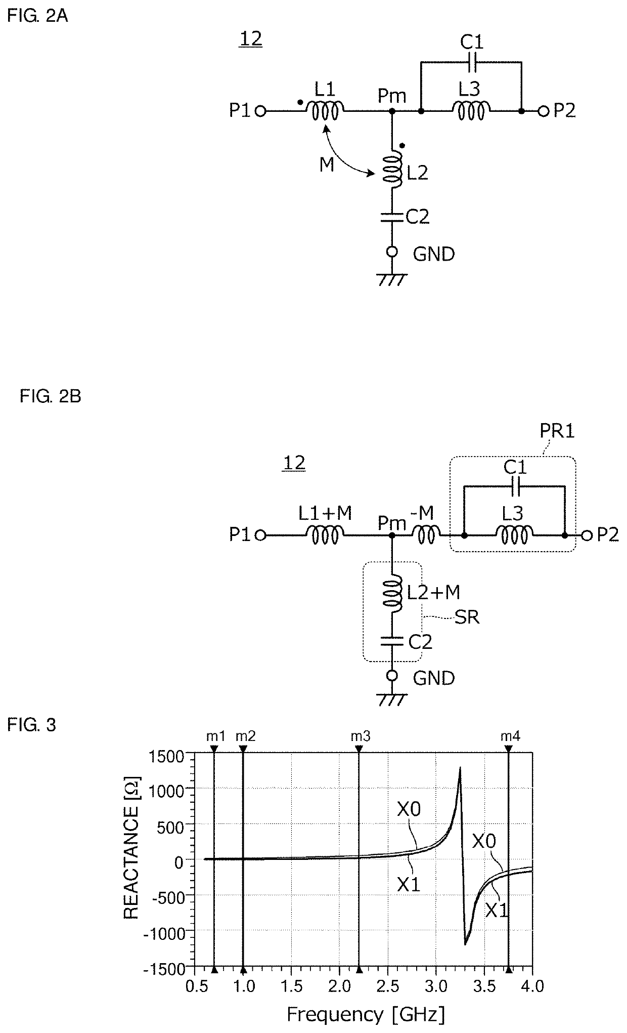
[0064]FIG. 2A is a circuit diagram of a low pass filter 12 according to the second preferred embodiment. FIG. 2B is an equivalent circuit diagram of the low pass filter 12.
[0065]The low pass filter 12 of the second preferred embodiment includes a first port P1, a second port P2, an intermediate node Pm between the first port P1 and the second port P2, and a ground terminal GND. Both the first port P1 and the second port P2 are input / output ports, and one is included in an input port, and the other is included in an output port.
[0066]Further, the low pass filter 12 includes a first inductor L1, a second inductor L2, a third inductor L3, a first capacitor C1, and a second capacitor C2.
[0067]The first inductor L1 is electrically connected between the first port P1 and the intermediate node Pm. The second inductor L2 is electrically connected between the inter...
third preferred embodiment
[0113]In a third preferred embodiment of the present invention, an example applied to a high pass filter will be described.
[0114]FIG. 5A is a circuit diagram of a high pass filter 13 according to the third preferred embodiment. FIG. 5B is an equivalent circuit diagram of the high pass filter 13.
[0115]The high pass filter 13 of the third preferred embodiment includes a first port P1, a second port P2, an intermediate node Pm between the first port P1 and the second port P2, and a ground terminal GND. Both the first port P1 and the second port P2 are input / output ports, and one is included in an input port, and the other is included in an output port.
[0116]Further, the high pass filter 13 includes a first inductor L1, a second inductor L2, a third inductor L3, and a third capacitor C3.
[0117]The first inductor L1 is electrically connected between the first port P1 and the intermediate node Pm. The second inductor L2 is electrically connected between the intermediate node Pm and the sec...
PUM
 Abstract
Description
Claims
Application Information
 - R&D
- Intellectual Property
- Life Sciences
- Materials
- Tech Scout
- Unparalleled Data Quality
- Higher Quality Content
- 60% Fewer Hallucinations
Browse by: Latest US Patents, China's latest patents, Technical Efficacy Thesaurus, Application Domain, Technology Topic, Popular Technical Reports.
© 2025 PatSnap. All rights reserved.Legal|Privacy policy|Modern Slavery Act Transparency Statement|Sitemap|About US| Contact US: help@patsnap.com


