Device and method for the production of a flat glass
a flat glass and production method technology, applied in the field of flat glass production devices and methods, can solve the problems of high tv, and achieve the effect of long glasses
- Summary
- Abstract
- Description
- Claims
- Application Information
AI Technical Summary
Benefits of technology
Problems solved by technology
Method used
Image
Examples
example 3
[0086]Furnace Faceplate with Preform Contact
[0087]In a redrawing unit a flat glass preform made of a heavy flint glass (NSF6) with the dimensions 1650 mm×340 mm×14 mm is redrawn to a thickness in the center region of 300 μm. The glass was of the following composition: SiO2 25% by weight, Na2O 10% by weight, K2O 10% by weight, CaO 10% by weight, BaO 10% by weight, TiO2 25% by weight, ZrO2 1% by weight, Nb2O5 5% by weight.
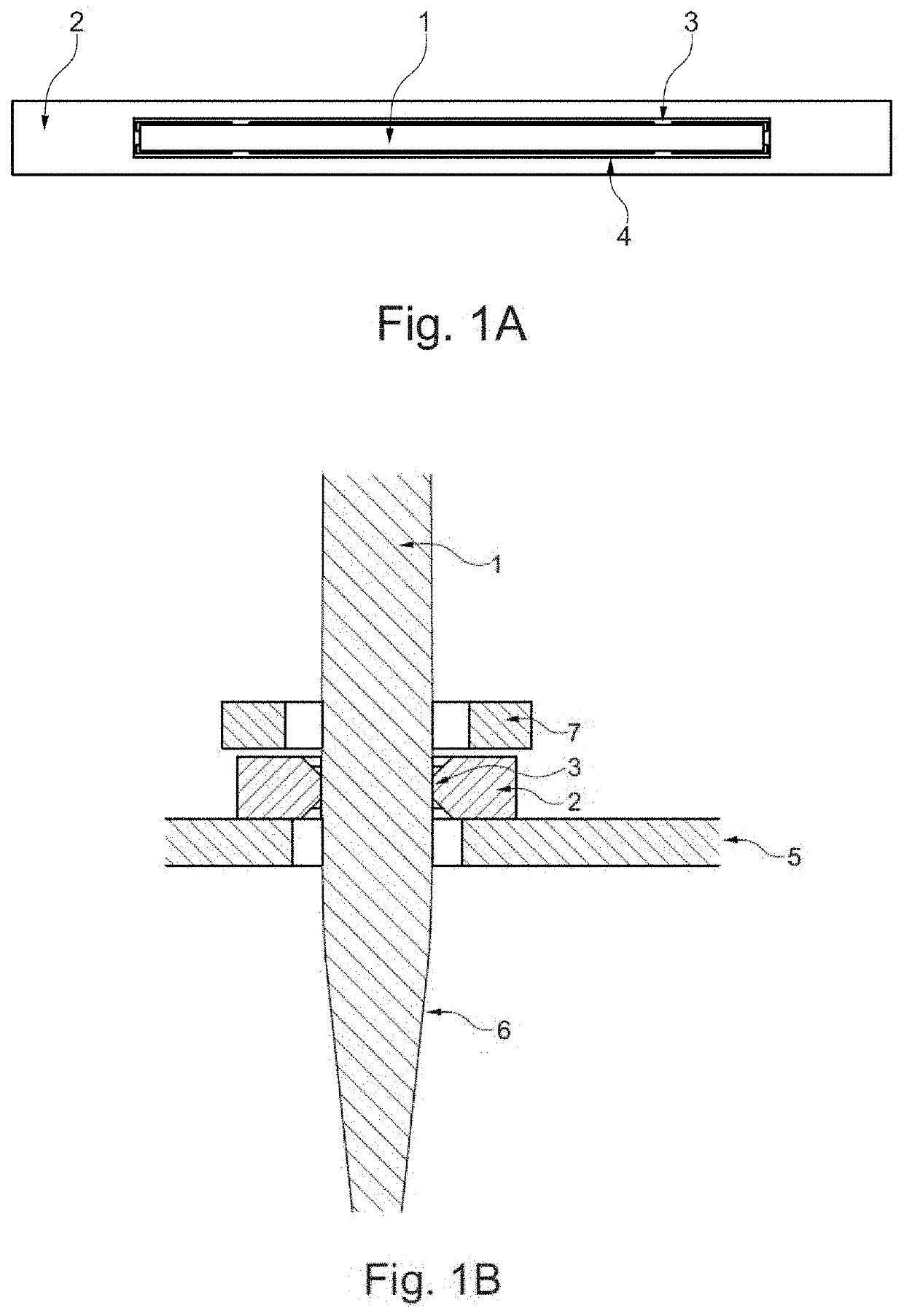
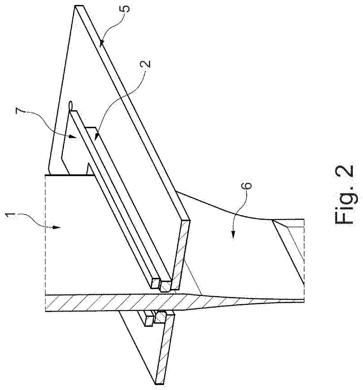
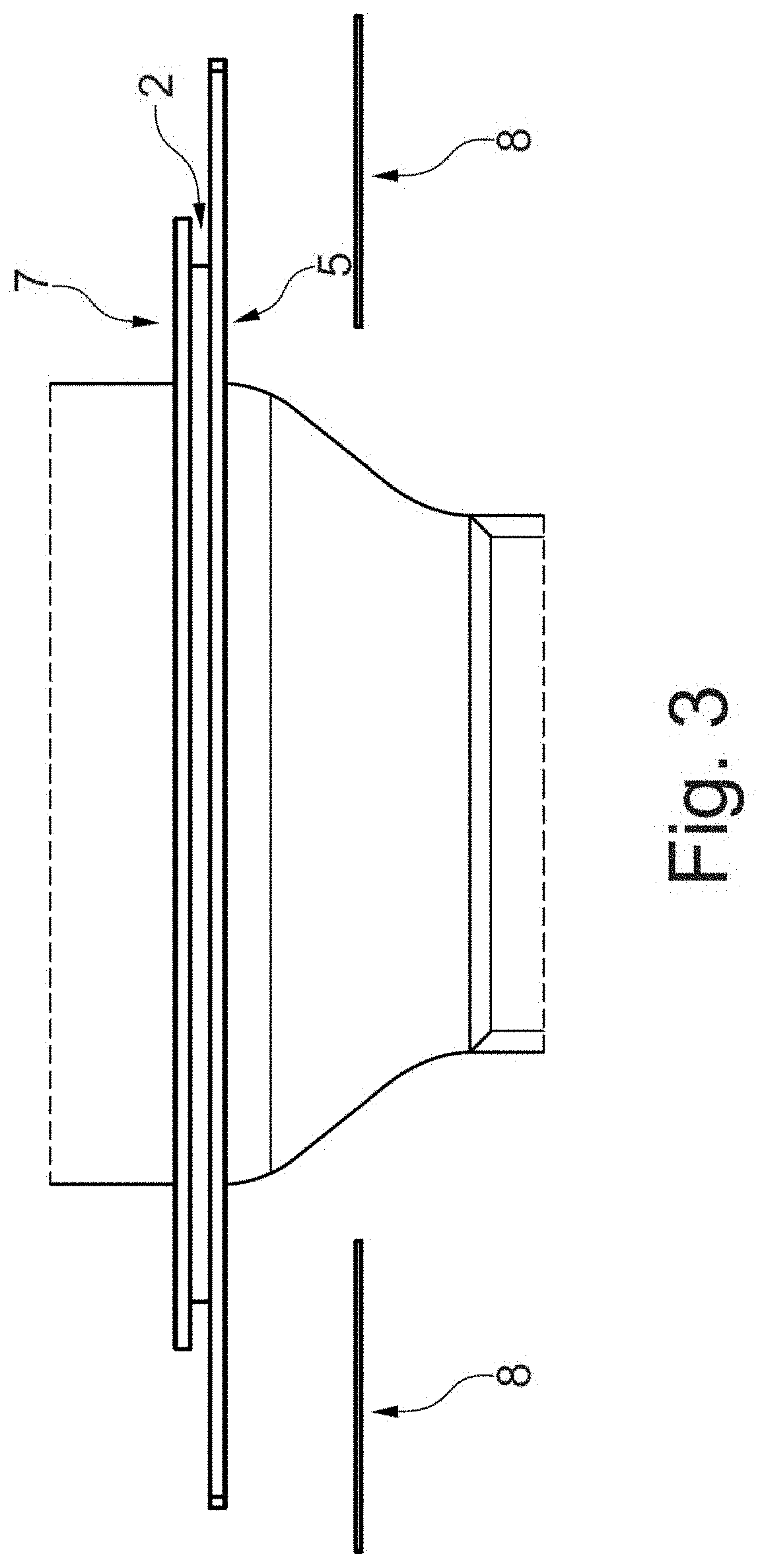
[0088]The redrawing unit is provided with a heating and cooling facility which results in a short deforming zone so that the width loss of the ribbon is lower than 80 mm. The heating facility consists of two parallel SiC tubes, the cooling facilities consist of furnace installations through which a coolant flows. Between the SiC tubes and besides the deforming zone of the glass, fast thermocouple elements for measuring the current temperature are arranged. Between the deforming zone and the preheating zone, a buoyant faceplate made of hexagonal boron nitride is insta...
example 4
[0090]Furnace Faceplate with Preform Contact, Cylindrical Elements
[0091]In a redrawing unit, a flat glass preform made of a heavy flint glass (NSF6) with the dimensions 1650 mm×340 mm×14 mm is redrawn to a thickness in the center region of 300 μm. The glass was of the following composition: SiO2 25% by weight, Na2O 10% by weight, K2O 10% by weight, CaO 10% by weight, BaO 10% by weight, TiO2 25% by weight, ZrO2 1% by weight, Nb2O5 5% by weight.
[0092]The redrawing unit is provided with a heating and cooling facility which results in a short deforming zone so that the width loss of the ribbon is lower than 80 mm. The heating facility consists of two parallel SiC tubes, the cooling facilities consist of furnace installations through which a coolant flows. Between the SiC tubes and besides the deforming zone of the glass, fast thermocouple elements for measuring the current temperature are arranged. Between the deforming zone and the preheating zone, a faceplate according to FIG. 4 is in...
example 5
[0094]Furnace Faceplate with Preform Contact
[0095]In a redrawing unit, a flat glass preform made of borosilicate glass (Borofloat) with the dimensions 1650 mm×340 mm×14 mm is redrawn to a thickness in the center region of 170 μm. The glass was of the following composition: SiO2 80% by weight, B2O3 12.5% by weight, Na2O 4% by weight, K2O 0.5% by weight, Al2O3 2% by weight.
[0096]The redrawing unit is provided with a heating and cooling facility which results in a short deforming zone so that the width loss of the ribbon is lower than 80 mm. The heating facility consists of two parallel SiC tubes, the cooling facilities consist of furnace installations through which a coolant flows. Between the SiC tubes and besides the deforming zone of the glass, fast thermocouple elements for measuring the current temperature are arranged. Between the deforming zone and the preheating zone, a buoyant faceplate made of hexagonal boron nitride is installed which touches the preform in the edge region ...
PUM
| Property | Measurement | Unit |
|---|---|---|
| width | aaaaa | aaaaa |
| thickness | aaaaa | aaaaa |
| thickness | aaaaa | aaaaa |
Abstract
Description
Claims
Application Information
 - R&D
- Intellectual Property
- Life Sciences
- Materials
- Tech Scout
- Unparalleled Data Quality
- Higher Quality Content
- 60% Fewer Hallucinations
Browse by: Latest US Patents, China's latest patents, Technical Efficacy Thesaurus, Application Domain, Technology Topic, Popular Technical Reports.
© 2025 PatSnap. All rights reserved.Legal|Privacy policy|Modern Slavery Act Transparency Statement|Sitemap|About US| Contact US: help@patsnap.com


