Al technical title is built by PatSnap Al team. It summarizes the technical point description of the patent document.
a technology of left atrial appendage and 3d image, which is applied in the direction of instruments, tomography, ultrasonic/sonic/infrasonic diagnostics, etc., can solve the problems of difficult interpretation of 2d projections of 3d objects, difficult laac, and limited anatomical understanding of 2d
Active Publication Date: 2020-08-20
ECHOPIXEL
View PDF0 Cites 7 Cited by
Summary
Abstract
Description
Claims
Application Information
AI Technical Summary
This helps you quickly interpret patents by identifying the three key elements:
Problems solved by technology
Method used
Benefits of technology
[0019]In a second group of embodiments, a computer may perform one or more measurements of an ostium or opening in an LAA, each of which may be perpendicular to the deepest visible point in the LAA, and one or more coordinates of a septal cross-section plan (e.g., where the septum is to be crossed in a surgical plan). Moreover, the computer may determine a route or path for how to navigate from the septum crossing to the ostium of the LAA. Alternatively or additionally, during a surgical procedure, in a first mode, a model of a device used to close an LAA may be registered to a patient's anatomy using, e.g., ultrasound (such as an echocardiogram or 2D TEE). Then, the model may be displayed, in real time, at the appropriate dynamic position and superimposed on or independently of the actual device in a 3D image and / or a simulated 2D fluoroscopy image. In some embodiments, landmarks may be displayed to assist the surgeon in the surgical procedure. Furthermore, in a second mode, the model may be removed from the 3D image and / or the simulated 2D fluoroscopy image.
Problems solved by technology
Unfortunately, 2D TEE usually provides limited anatomical understanding.
More generally, 2D projections of a 3D object (such as 2D TEE or fluoroscopy) are often difficult to interpret.
Consequently, uncertainty can be added to the device sizing, the surgical plan, and the procedure itself, which can make LAAC more challenging and can adversely impact patient outcomes.
Method used
Image
Click on the blue label to locate the original text in one second.
Reading with bidirectional positioning of images and text.
Examples
Embodiment Construction
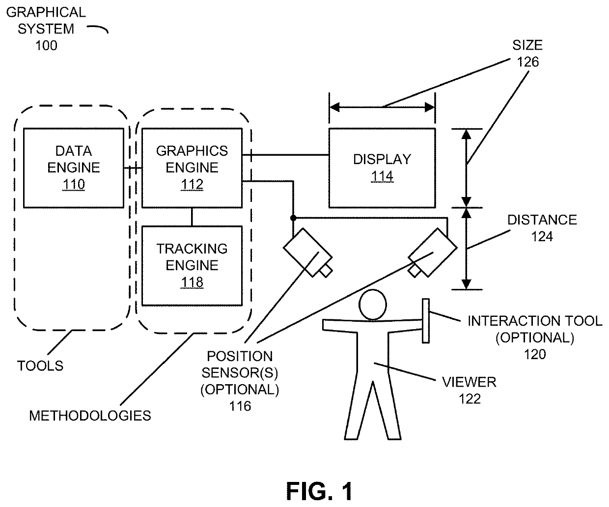
[0051]Human perception of information about the surrounding environment contained in visible light (which is sometimes referred to as ‘eyesight,’‘sight,’ or ‘vision’) is facilitated by multiple physiological components in the human visual system, including senses that provide sensory inputs and the cognitive interpretation of the sensory inputs by the brain. The graphical system in the present application provides rendered images that intuitively facilitate accurate human perception of 3D visual information (i.e., the awareness of an object or a scene through physical sensation of the 3D visual information). Notably, the graphical system in the present application provides so-called True 3D via rendered left-eye and right-eye images that include apparent image parallax (i.e., a difference in the position of the object or the scene depicted in the rendered left-eye and the right-eye images that approximates the difference that would occur if the object or the scene were viewed along ...
PUM
Abstract
A computer that determines at least an anatomic feature of a left atrial appendage (LAA) is described. During operation, the computer generates a 3D image associated with an individual's heart. This 3D image may present a view along a perpendicular direction to an opening of the LAA. Then, the computer may receive information specifying a set of reference locations. For example, the set of reference locations may include: a location on a circumflex artery, a location between a superior portion of the LAA and a left pulmonary vein, and/or a location on a superior wall of the LAA and distal to trabeculae carneae. Next, the computer automatically determines, based, at least in part, on the set of reference locations, at least the anatomical feature of the LAA, which is associated with the opening of the LAA and a size of a device used in an LAA closure (LAAC) procedure.
Description
CROSS REFERENCE TO RELATED APPLICATION[0001]This application claims the benefit of U.S. Provisional Application No. 62 / 805,961, entitled “Left-Atrial-Appendage Annotation Using 3D Images,” by Anthony Chen, et al., filed Feb. 15, 2019, the contents of which are hereby incorporated by reference.[0002]This application is related to: U.S. patent application Ser. No. ***, “Glasses-Free Determination of Absolute Motion,” filed on Feb. 8, 2019; U.S. patent application Ser. No. 16 / 101,416, “Multi-Point Annotation Using a Haptic Plane,” filed on Aug. 11, 2018; U.S. patent application Ser. No. 16 / 101,417, “Multi-Point Annotation Using a Haptic Plane,” filed on Aug. 11, 2018; and U.S. patent application Ser. No. 14 / 120,519, “Image Annotation Using a Haptic Plane,” filed on May 28, 2014, the contents of each of which are herein incorporated by reference.BACKGROUNDField[0003]The described embodiments relate to computer-based techniques for annotating one or more features based at least in part o...
Claims
Application Information
Patent Timeline
Application Date:The date an application was filed.
Publication Date:The date a patent or application was officially published.
First Publication Date:The earliest publication date of a patent with the same application number.
Issue Date:Publication date of the patent grant document.
PCT Entry Date:The Entry date of PCT National Phase.
Estimated Expiry Date:The statutory expiry date of a patent right according to the Patent Law, and it is the longest term of protection that the patent right can achieve without the termination of the patent right due to other reasons(Term extension factor has been taken into account ).
Invalid Date:Actual expiry date is based on effective date or publication date of legal transaction data of invalid patent.
Patent Type & Authority Applications(United States)