Centrifugation method

Inactive Publication Date: 2020-08-27
JO HYUN CHUL
View PDF0 Cites 0 Cited by
  • Summary
  • Abstract
  • Description
  • Claims
  • Application Information

AI Technical Summary

Benefits of technology

[0030]By the centrifugation method according to the present invention, after extracting the blood by using a separate tool, the blood extracted by the injector is directly injected into the centrifugal container to be subjected to a centrifugation process without a need to transfer the blood to another storage container or tube and a specific component, for example, platelet rich plasma (PRP) can be directly separated from the centrifugal container and immediately extracted without a movement process. Through such a process, it is possible to more hygienically, quickly, and simply extract the specific component from the object to be treated.
[0031]Furthermore, according to the present invention, since the boundary layer component can be separated through the nozzle blocking while confirming the height of the boundary layer component passing through the nozzle, it is possible to precisely adjust the composition ratio of the target component. In particular, in recent years, it has been known that the characteristics of platelet rich plasma (PRP) depend greatly on the presence or absence of leukocyte and it is possible to manufacture leukocyte poor PRP or leukocyte rich PRP according to a required situation and it is possible to adjust purity of the PRP.
[0032]Further, according to the present invention, the second specific component is extracted from the first space while the nozzle is blocked to adjust the concentration degree of the boundary la

Problems solved by technology

However, in the related art, there is a problem that an extraction process of extracting a specific component such as platelets from the blood is troublesome and inconvenient.
Therefore, in order to extract the platelets, it is inconvenient and cumbersome to undergo centrifugation processes in at least two different centrifugal spaces, and since the blood needs to be transferred in the centrifugation process, there is a problem that the blood is exposed to the outside.
In addition, in the related art, there is a problem that it is difficult to perform a procedure using the specific component immediately after separating a specific comp

Method used


Image

  • Centrifugation method
  • Centrifugation method
  • Centrifugation method

Examples


Example

MODES OF THE INVENTION

[0051]Hereinafter, embodiments of the present invention will be described in detail with reference to the accompanying drawings, but the present invention is not limited or restricted to the embodiments. In describing the present invention, a detailed description of well-known functions or configurations may be omitted for clarity of the present invention.

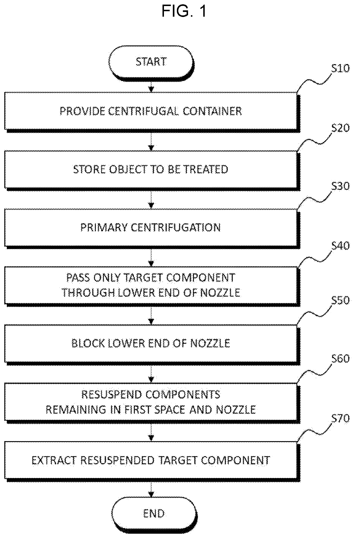
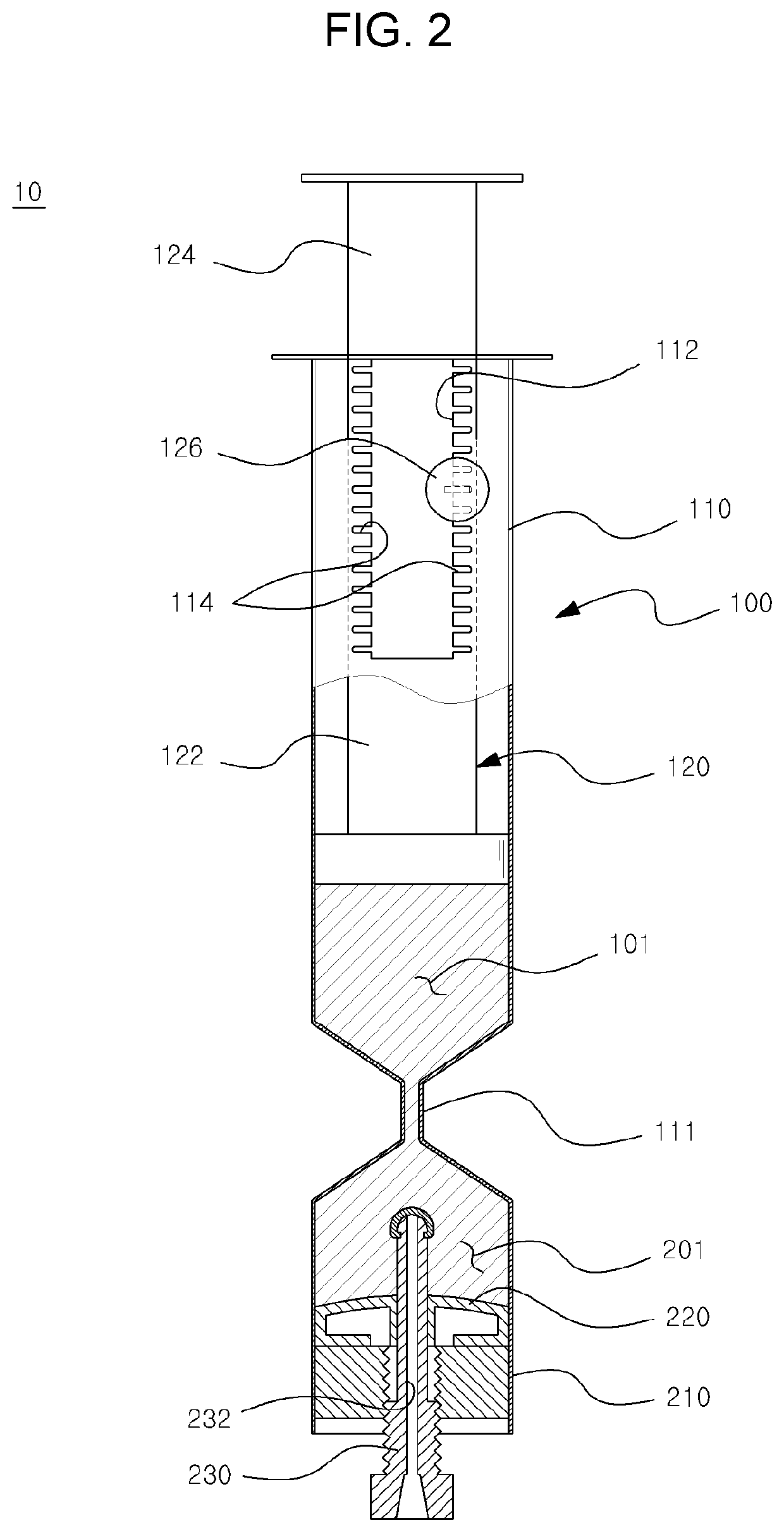
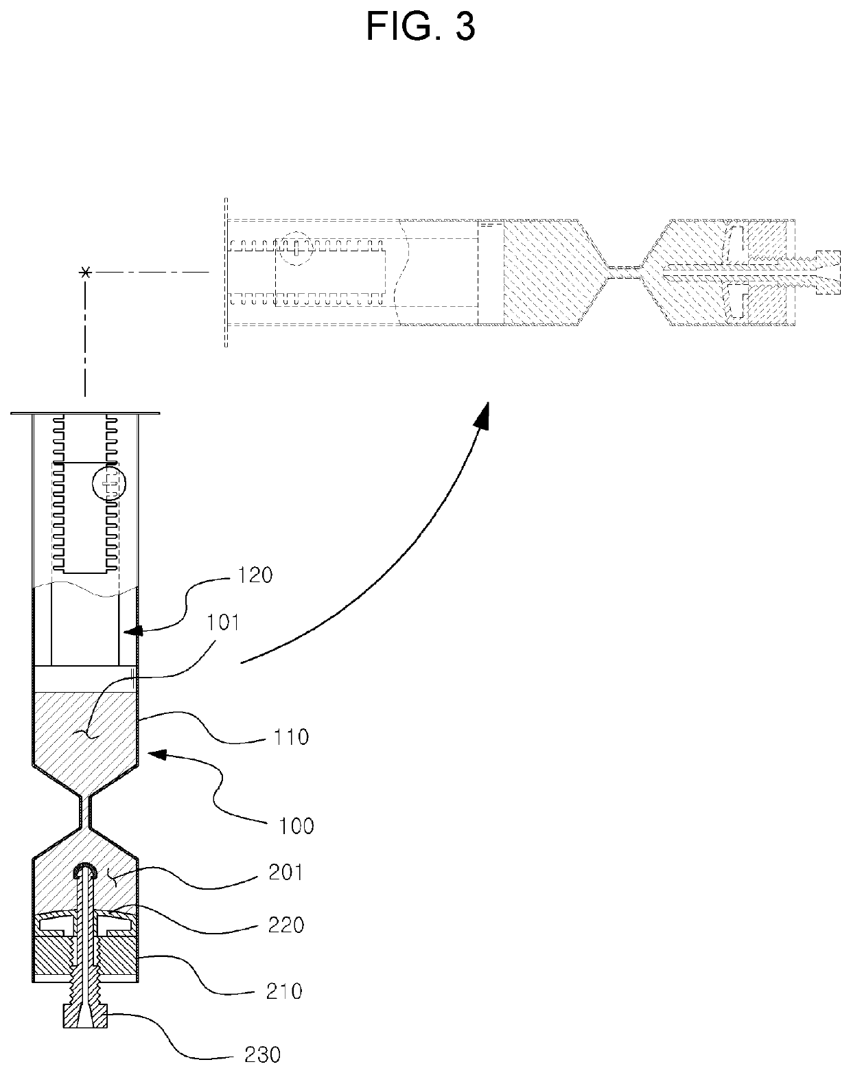
[0052]FIG. 1 is a block diagram for describing a centrifugation method according to an embodiment of the present invention, FIG. 2 is a view for describing a storage state of an object to be treated, as the centrifugation method according to an embodiment of the present invention, and FIGS. 3 and 4 are views for describing a centrifugation process and a state of interlayer separation of an object to be treated by centrifugation, as the centrifugation method according to an embodiment of the present invention. FIG. 5 is a view for describing movement of a boundary layer by volume variation of a first space and ...


PUM


Abstract

Provided is a centrifugation method for extracting a target component from an object including: providing a centrifugal container including a first space in an upper portion, a second space in a lower portion, a nozzle connecting the first space and the second space, a second plunger movably received in the second space, and a nozzle blocking member to penetrate the center of the second plunger in a longitudinal direction and to linearly move on the second plunger to selectively open/close a lower end of the nozzle; storing the object; interlayer-separating the object by primarily centrifuging the object; passing only the target component in the object; blocking the lower end of the nozzle by means of the nozzle blocking member; resuspending components remaining in the first space and the nozzle while the nozzle is blocked; and extracting a target component resuspended in the first space.

Description

TECHNICAL FIELD[0001]The present invention relates to a centrifugation method, and more particularly, to a centrifugation method capable of more quickly and simply centrifuging an object to be treated and a centrifugal container capable of compactly implementing such centrifugation.TECHNICAL FIELD[0002]In general, the blood may be divided into blood cells, which are solid components, and plasma, which is a liquid component. The blood cells are composed of red blood cells, white blood cells and platelets, and the plasma is mainly composed of water, which includes blood coagulation factors and electrolytes, required for life maintenance.[0003]The blood is a mixture of various components, and a process of separating the blood and extracting specific components for various medical purposes is widely used, in which a blood centrifuging process using a centrifuge and a process of using a specific composition have been widely used.[0004]Among them, the blood centrifuging process means a pr...

Claims


Application Information

Patent Timeline
IPC IPC(8): B04B5/04B04B11/02
CPCB04B5/0442B04B11/02B04B2005/0485A61M1/029A61M1/3693A61M2202/0427B01L3/5021B01L2200/026B01L2400/0478B01L2400/0633
Inventor JO, HYUN CHUL
Owner JO HYUN CHUL
Why Eureka
Try Eureka