
System for measuring a bending deformation of a surface of a material

a technology of a surface and a measuring system, which is applied in the direction of measuring the strength of materials using steady bending forces, mechanical counters/curvatures, instruments, etc., can the proximity of sensors to test pieces does not solve the problem of high temperature test, and the amplitude of deformation increases during the test. problem, to achieve the effect of reliable and repeatable deformation measurement, without risking the deformation of the sensor

Active Publication Date: 2020-08-27
SN DETUDE & DE CONSTR DE MOTEURS DAVIATION S N E C M A
View PDF0 Cites 2 Cited by
  • Summary
  • Abstract
  • Description
  • Claims
  • Application Information

AI Technical Summary

Benefits of technology

The patent describes a way to measure the deformation of a material using a high-quality sensor that remains remote from the material being tested. This allows for the measurement of deformation at different ratios and also allows for the testing of materials at high temperatures without damaging the sensor. The technical effect of this patent is the ability to accurately measure the deformation of materials using a non-destructive approach.

Problems solved by technology

One problem with force controlling is that, however, the amplitude of deformation increases during the test.
However, the spaces existing in current testing machines are too small to be able to insert these sensors.
However, these gauges are sensitive to temperature, which can make them unusable depending on the thermal conditions of the tests, and have a lifetime generally shorter than the lifetime of the test.
The proximity of the sensors to the test piece does not, however, solve the problem of performing high temperature tests.
One disadvantage is that during the overall displacement of the test piece, the strain gage has a rotational movement which introduces an error in measuring the curvature.

Method used


Image

  • System for measuring a bending deformation of a surface of a material
  • System for measuring a bending deformation of a surface of a material
  • System for measuring a bending deformation of a surface of a material

Examples


Embodiment Construction

[0054]A first object of the invention relates to a system for measuring a bending deformation of a surface of a material.

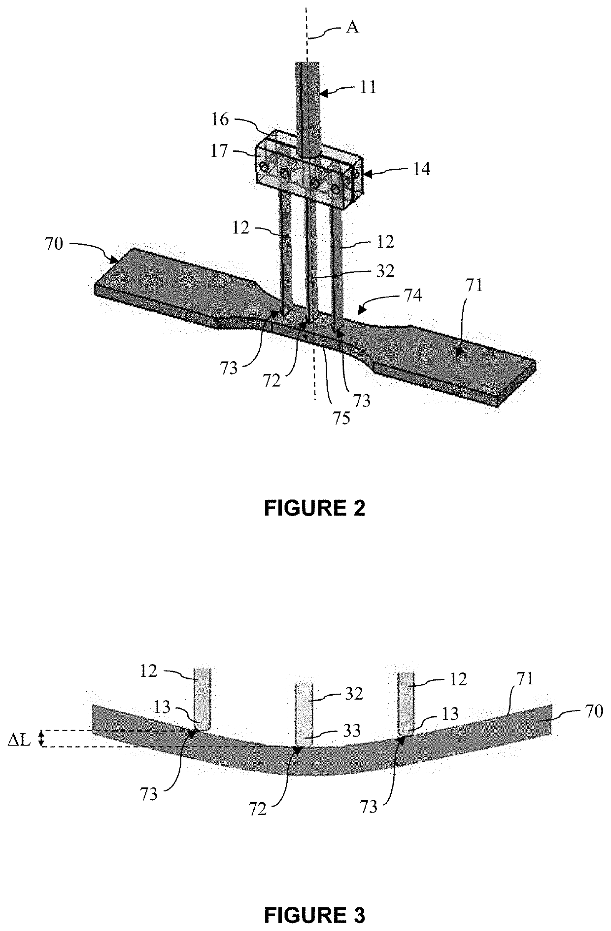
[0055]The measurement system is integrated into a bending surface deformation test system, in which it is configured to cooperate with a bending test machine and a four-point bending mounting allowing to deform a test piece of said material.

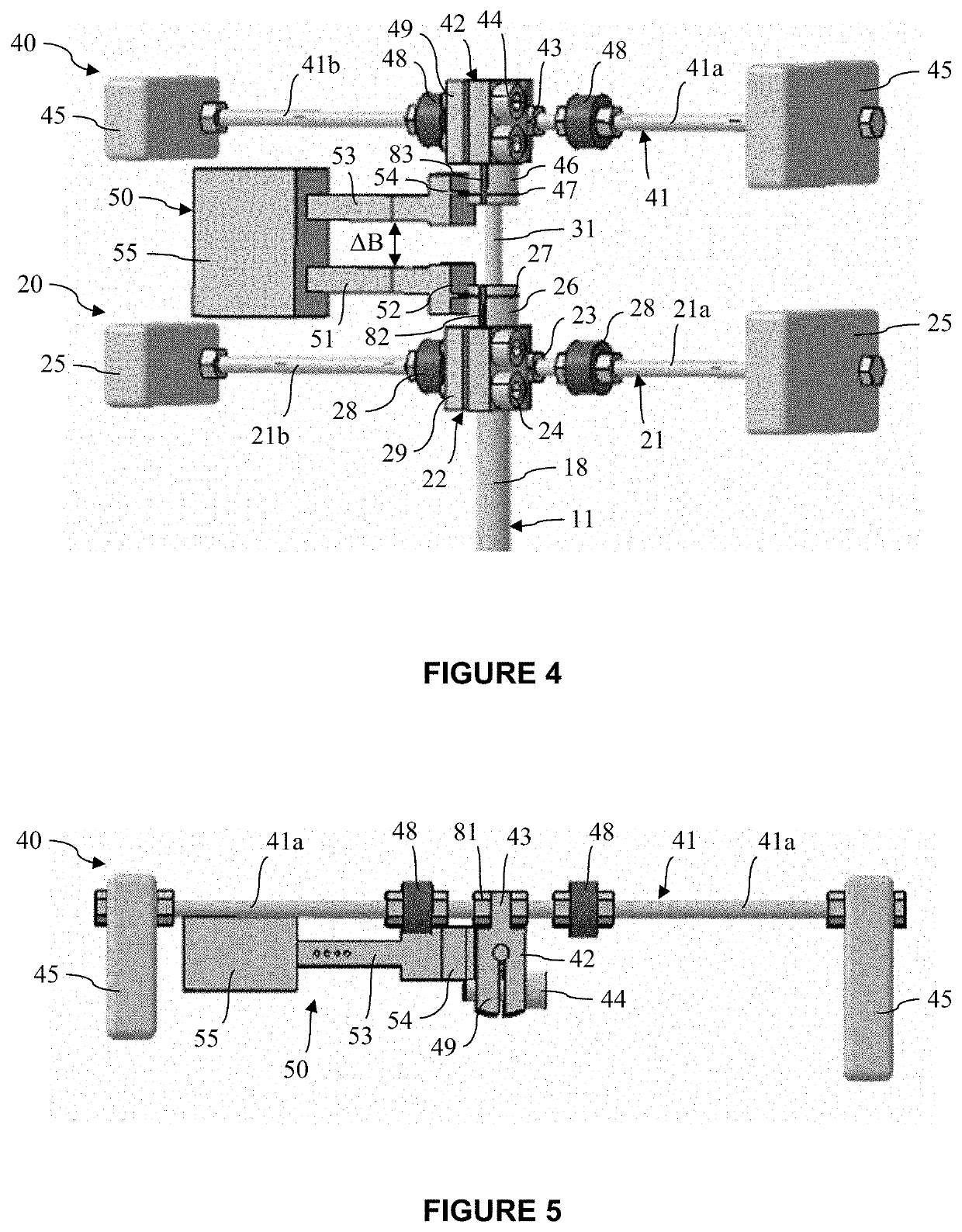
[0056]The principle of a four-point mounting is as follows. During a bending deformation test, a testing machine imposes via a force cell a mechanical constraint on a useful central portion of the upper surface of the test piece at two pressure points, while lateral portions of the lower surface are supported on the two other bearing points of the mounting.

[0057]The test piece thus deforms under mechanical constraint. The upper surface whose deformation is studied thus undergoes a compressive constraint, while the lower surface undergoes a traction constraint.

[0058]Compared to a three-point bending test, the four-point bending ...


PUM


Abstract

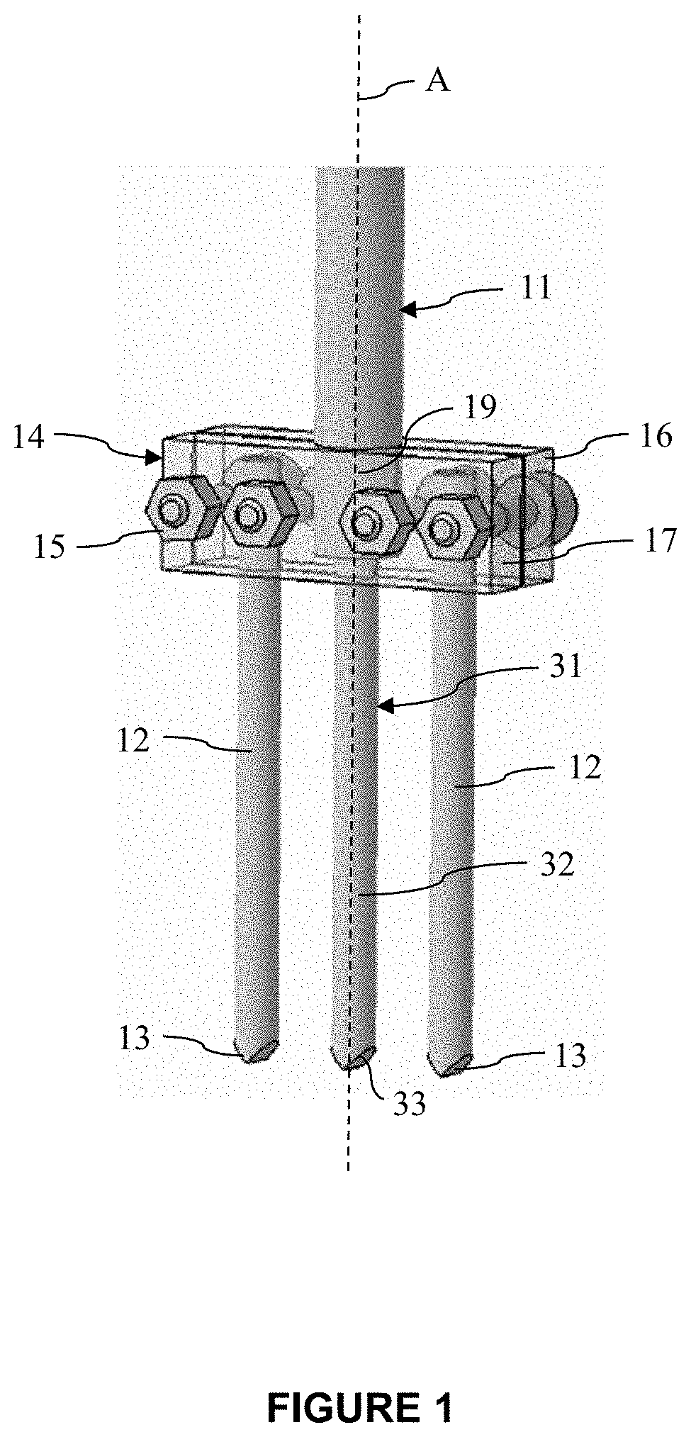
A system for measuring a bending deformation of a surface of a material which cooperates with a bending test machine to deform a test piece. The system includes a first portion with lateral teeth which bear against an upper surface of the test piece. A first load support connected to the lateral teeth applies a constant force towards the test piece. A second portion with a central tooth bears against the upper surface. A second load support connected to the central tooth applies a constant force oriented towards the test piece. A measuring device includes a deformation sensor having a first arm connected to the first portion, and a second arm connected to the second portion. The first arm and the second arm are separated from each other by a variable distance (AB) measured by the measuring device.

Description

TECHNICAL FIELD OF THE INVENTION[0001]The present invention relates to the field of bending tests of mechanical parts, and more particularly the measurement of the bending deformation of a surface of these parts during the implementation of such tests.STATE OF THE ART[0002]Bending tests are commonly used in the industry in order to fatigue test the surface of materials. In other words, these tests allow studying the bending mechanical strength of the surface of materials. The material to be studied is typically in the form of a test piece, the dimensions of which are adapted to those of testing machines.[0003]These tests are generally force controlled. One problem with force controlling is that, however, the amplitude of deformation increases during the test.[0004]A solution to this problem is to control the deformation tests. Measuring the curvature of the test piece when it deforms requires at least two sensors, typically LVDT (linear variable differential transformer) sensors spa...

Claims


Application Information

Patent Timeline
IPC IPC(8): G01B5/30G01B5/20G01N3/20G01B5/16
CPCG01B5/20G01B5/16G01N3/20G01B5/30G01B7/16G01B21/32G01N3/062
Inventor BROSSIER, PASCAL NOELBOUISSOU, PIERREHENRY, JOSEPHMULLER, REMYPUJOL D'ANDREBO, QUENTIN
Owner SN DETUDE & DE CONSTR DE MOTEURS DAVIATION S N E C M A
Learn More