
Utility knife with a locknut

a technology of utility knives and lock nuts, which is applied in the field of knives, can solve the problems of affecting the use of knives, the function of locking blades is disabled, and the lock structure is not particularly secured, and achieves the effects of preventing the blade from sliding freely or injuring users or others accidentally, simple structure, and saving user's effort of manual pressing and limiting the blade for its operation

Active Publication Date: 2020-09-03
NINGBO HONGDI MEASURING TAPE IND CO LTD
View PDF0 Cites 9 Cited by
  • Summary
  • Abstract
  • Description
  • Claims
  • Application Information

AI Technical Summary

Benefits of technology

The present invention provides a utility knife with a locking mechanism to secure the blade in place. The knife has a simple structure and is easy to operate. The locking mechanism includes a locking rod and an adjusting device, which can be fixed to the case and adjusted to lock the blade. The locking mechanism securely locks the blade and prevents it from moving or retracting. The knife also has a blade holder with a slidable mounting groove and a movable pushbutton. The locking mechanism is conveniently located near the blade extension / retraction opening, making it easy to lock the blade. The technical effects of the invention are improved safety and convenience in using the knife.

Problems solved by technology

However, such locking structure is not particularly secured.
When the movable pushbutton is touched by accident during the use of the knife, the blade may be released from the unlocked state easily, and an elastic resetting member may be malfunctioned during a locking process, so that the function of locking the blade is disabled.
Furthermore, the blade may be shaken during the use of the knife because there is a gap existing between the blade and the blade chute.
As a result, a general utility knife is not suitable for fine cutting.

Method used


Image

  • Utility knife with a locknut
  • Utility knife with a locknut
  • Utility knife with a locknut

Examples


Embodiment Construction

[0037]To make it easier for our examiner to understand the objective of the invention, its structure, innovative features, and performance, we use a preferred embodiment together with the attached drawings for the detailed description of the invention.

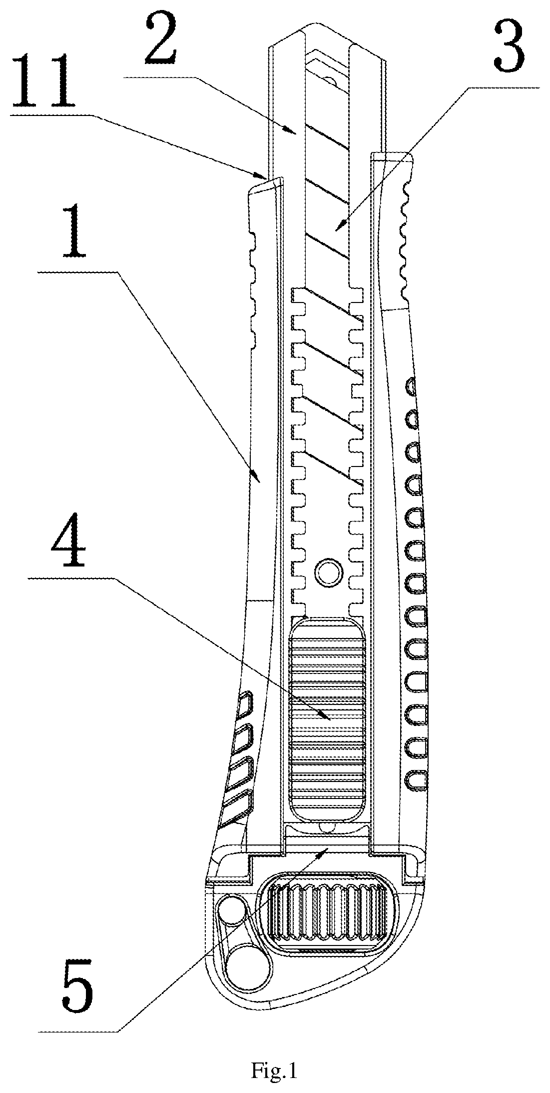
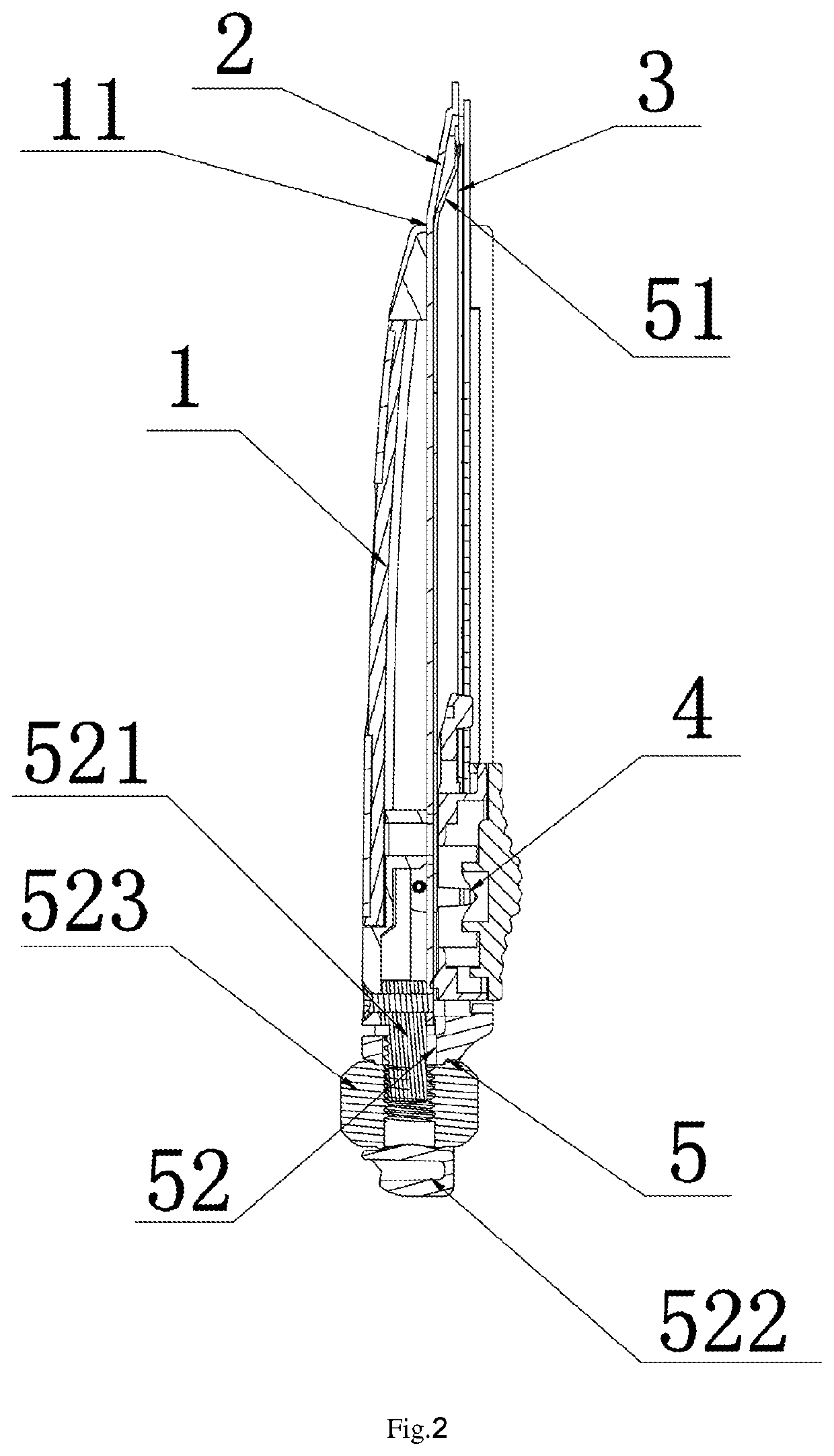
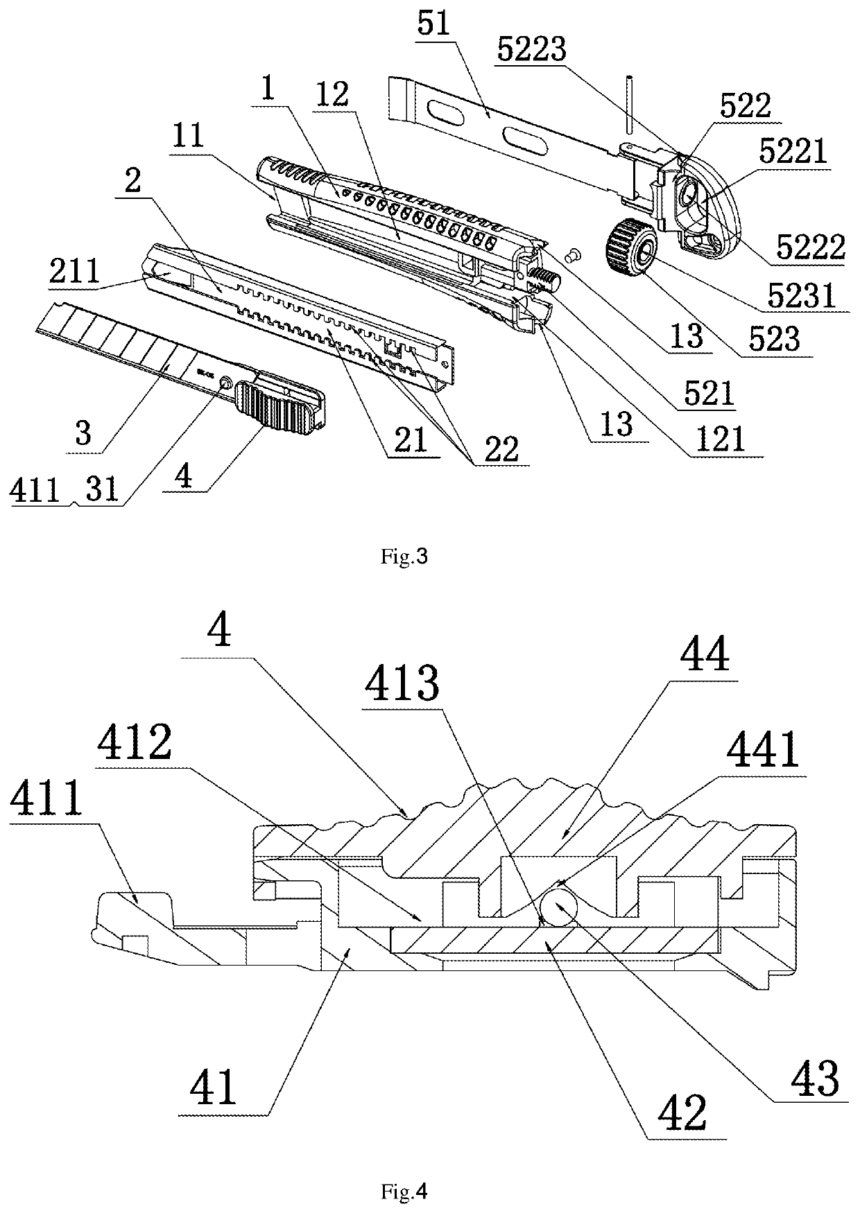
[0038]With reference to FIGS. 1 to 3 for a schematic view, a cross-sectional view, and an exploded view of a utility knife with a locknut of the present invention respectively, FIG. 4 for a schematic view of a movable pushbutton of a utility knife with a locknut of the invention, FIG. 5 for a case of a utility knife with a locknut of the invention, FIG. 6 for another utility knife with a locknut of the invention, FIG. 7 is a schematic view of a utility knife with a locknut and without a left case of the invention, FIG. 8 is a schematic view of a utility knife with a locknut and without a right case of the invention, the utility knife with a locknut comprises a case 1, a blade holder 2, a blade 3, a movable pushbutton 4 and a locking de...


PUM


Abstract

A utility knife with a locknut includes a case, a blade holder, a blade, a movable pushbutton and a locking device. A blade extension / retraction opening is formed at a front end of the case and provided for the blade to extend or retract, and a movable chute is formed on a side of the case and provided for the movable pushbutton to move. The blade is correspondingly installed in the case by the blade holder, the blade controls its extension and retraction in the blade extension / retraction opening by the movable pushbutton. The locking device includes a locking rod and an adjusting device and uses the adjusting device to adjust the locking rod and lock the blade.

Description

FIELD OF INVENTION[0001]The present invention relates to the technical field of knives, in particular to a utility knife with a locknut.BACKGROUND OF INVENTIONDescription of the Related Art[0002]Utility knife, also known as craving knife or wallpaper knife, is a knife generally used in the areas of fine arts and handcrafts and mainly used for cutting a relatively soft object, and most of such knives are comprised of a plastic knife handle and a blade and have a pull-out structure. There are also a few of them having a metal knife handle, and most of the blades have an oblique end and use a smooth blunt sheet body for drawing lines, cutting, and show a new blade to facilitate the use of the knife. In general, most conventional utility knives adopt a latching effect between a movable pushbutton and a locking serration formed on a blade chute to achieve the purpose of locking the blade. However, such locking structure is not particularly secured. When the movable pushbutton is touched ...

Claims


Application Information

Patent Timeline
Patent Type & Authority Applications(United States)
IPC IPC(8): B26B1/08B26B1/04B26B5/00
CPCB26B1/08B26B5/003B26B1/048B26B5/002B26B5/001
Inventor ZHOU, XIAOGANG
Owner NINGBO HONGDI MEASURING TAPE IND CO LTD
Learn More