Waveform analyzer

Active Publication Date: 2020-09-03
SHIMADZU CORP
View PDF0 Cites 4 Cited by
  • Summary
  • Abstract
  • Description
  • Claims
  • Application Information

AI Technical Summary

Benefits of technology

[0036]The waveform analyzer according to the present invention eliminates the necessity of cumbersome tasks required in the various conventional peak detection algorithms, such as the tuning of the parameters for the detection, or the selection of an appropriate algorithm. The operator does not need to visually check the signal waveform and manually set the starting and ending points of the peak. Since personal habits or intentional operations by the operat

Problems solved by technology

An actual chromatogram waveform has such problems as the superposition of various types of noise, fluctuation of the baseline, or overlap of the peaks originating from a plurality of kinds of components.
Therefore, it is difficult to correctly detect a peak from a chromatogram waveform.
Furthermore, since it is from the start difficult to apply a single specific algorithm to chromatogram waveforms which vary in baseline shape or peak shape, the operator also needs to select an algorithm to be used from a plurality of peak detec

Method used


Image

  • Waveform analyzer
  • Waveform analyzer
  • Waveform analyzer

Examples


Embodiment Construction

[0044]One embodiment of the waveform analyzer according to the present invention is hereinafter described in detail.

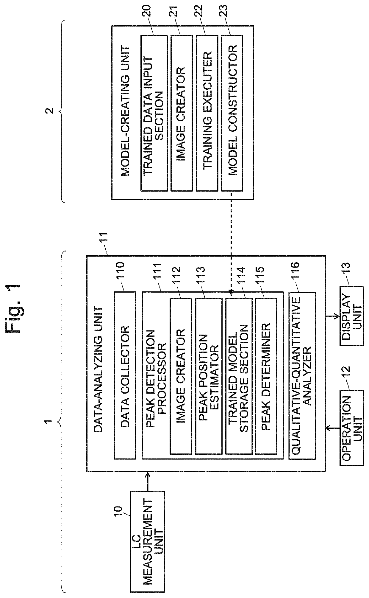
[0045]FIG. 1 is a schematic configuration diagram of a liquid chromatograph (LC) system using one embodiment of the waveform analyzer according to the present invention and a system for creating a trained model to be used in the LC system.

[0046]The LC system 1 includes an LC measurement unit 10, data-analyzing unit 1L operation unit 12 and display unit 13. Though not shown, the LC measurement unit 10 includes a liquid supply pump, injector, column, column oven, detector and other components. The LC measurement unit 10 performs an LC analysis on a given sample and acquires chromatogram data which show the temporal change of the intensity of the signal produced by the detector. The data-analyzing unit 11 includes a data collector 110, peak detection processor 111, qualitative-quantitative anlalyzer 116 and other functional blocks. The peak detection processor 111 further...


PUM


Abstract

A model constructed by a training process using the technique of deep learning using the training data including images created from a large number of chromatograms and correct peak information is previously stored in a trained model storage section. When chromatogram data for a target sample acquired with an LC measurement unit are inputted, an image creator converts the chromatogram into an image and creates an input image in which one of the two areas divided by the chromatogram curve as the boundary in the image is filled. A peak position estimator inputs the pixel values of the input image into a trained model using a neural network, and obtains the position information of the starting point and/or ending point of the peak and a peak detection confidence as the output. A peak determiner determines the starting point and/or ending point of each peak based on the peak detection confidence.

Description

TECHNICAL FIELD[0001]The present invention relates to a waveform analyzer configured to analyze the waveform of a signal acquired with an analyzing device. For example, the present invention is suitable for an analysis of the waveform of a signal acquired with various analyzing devices, such as a chromatogram waveform acquired with a gas chromatograph (GC), liquid chromatograph (LC) or similar apparatus, a mass-spectrum waveform acquired with a mass spectrometer, an absorption-spectrum waveform acquired with a spectrophotometer or similar apparatus, as well as an X-ray-spectrum waveform acquired with an X-ray analyzer.BACKGROUND ART[0002]In a gas chromatograph or liquid chromatograph apparatus, a sample containing various components is introduced into a column. While the sample is passing through the column, the various components are separated from each other in the temporal direction. The separated components are detected with a detector located at the exit end of the column. Base...

Claims


Application Information

Patent Timeline
IPC IPC(8): G06T11/00G06T7/12G06T7/70G06N3/04G06N3/08
CPCG06T7/70G06N3/04G06T2207/20221G06T7/12G06N3/08G06T11/001G06T2207/10016G06T2207/20084G06T2207/20081G01N30/86G06T11/206G06V10/454G06V10/82G06N3/045G06F2218/10
Inventor OSOEKAWA, TAKESHIHIDA, YUSUKEKANAZAWA, YUZIKANAZAWA, SHINJIYAMADA, YOHEIYASUDA, HIROYUKIKUNISAWA, AKIHIROTERADA, HIDETOSHI
Owner SHIMADZU CORP
Why Eureka
Try Eureka