Assembly Formed By A Bone Anchoring Base Belonging to a Prosthetic Joint and by at Least One Screw Fastening This Base to a Bone

a technology of bone anchoring and prosthetic joints, applied in the field of joint assembly, can solve the problems of insufficient anchoring of the screw in the bone, and insufficient anchoring of the base to the bon

Inactive Publication Date: 2020-09-17
FX SHOULDER USA INC
View PDF0 Cites 5 Cited by
  • Summary
  • Abstract
  • Description
  • Claims
  • Application Information

AI Technical Summary

Benefits of technology

[0016]The assembly according to at least some embodiments thus allows ideal placement of such a glenoid base on a scapula, which is important for the proper operation of the prosthetic shoulder.

Problems solved by technology

The insertion of the anchoring stud in the cancellous bone makes it possible to guarantee a certain immobilization of the base relative to the bone, but it is not sufficient to withstand all of the repeated forces exerted on the prosthesis part due to movements by the patient; it is therefore necessary to guarantee this immobilization using one or several anchoring screws passing through the base.
Such a prosthesis has the drawback of a risk of the anchoring screw, during the placement thereof, not being perfectly coaxial with the protrusion, which, during tightening of the screw, creates tensions between the base and the bone that are not very favorable to the proper anchoring of the prosthesis to the bone.
Furthermore, in case of poor quality cancellous bone, the placement of the screw may lead to damage of this bone by the thread of the screw during the placement of this screw, particularly if the screwing process is continued while the head of the screw has come into contact with the distal wall of the protrusion defining the free end of this protrusion; this results in insufficient anchoring of the screw in the bone, and therefore insufficient anchoring of the base to the bone.

Method used


Image

  • Assembly Formed By A Bone Anchoring Base Belonging to a Prosthetic Joint and by at Least One Screw Fastening This Base to a Bone
  • Assembly Formed By A Bone Anchoring Base Belonging to a Prosthetic Joint and by at Least One Screw Fastening This Base to a Bone
  • Assembly Formed By A Bone Anchoring Base Belonging to a Prosthetic Joint and by at Least One Screw Fastening This Base to a Bone

Examples


Embodiment Construction

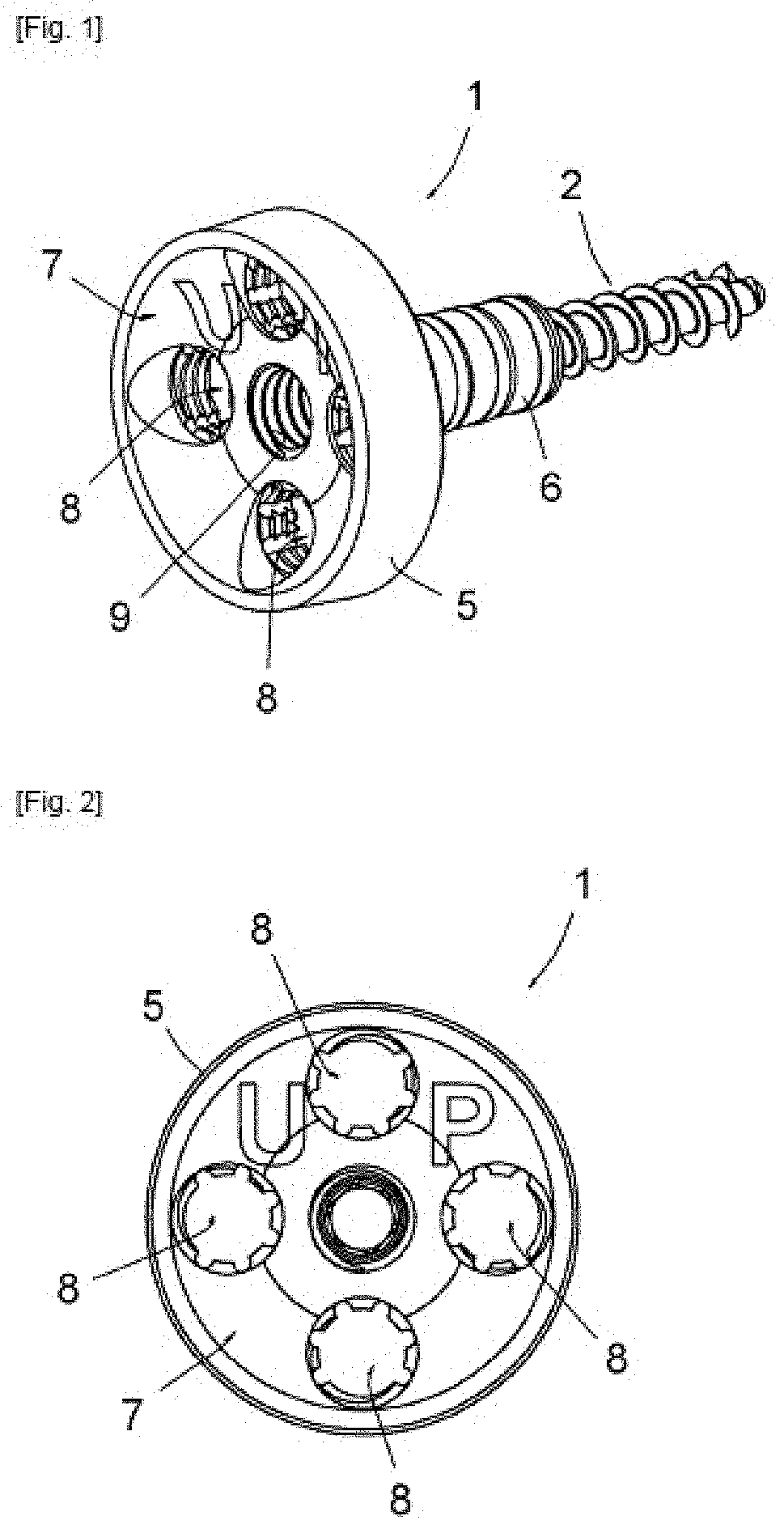
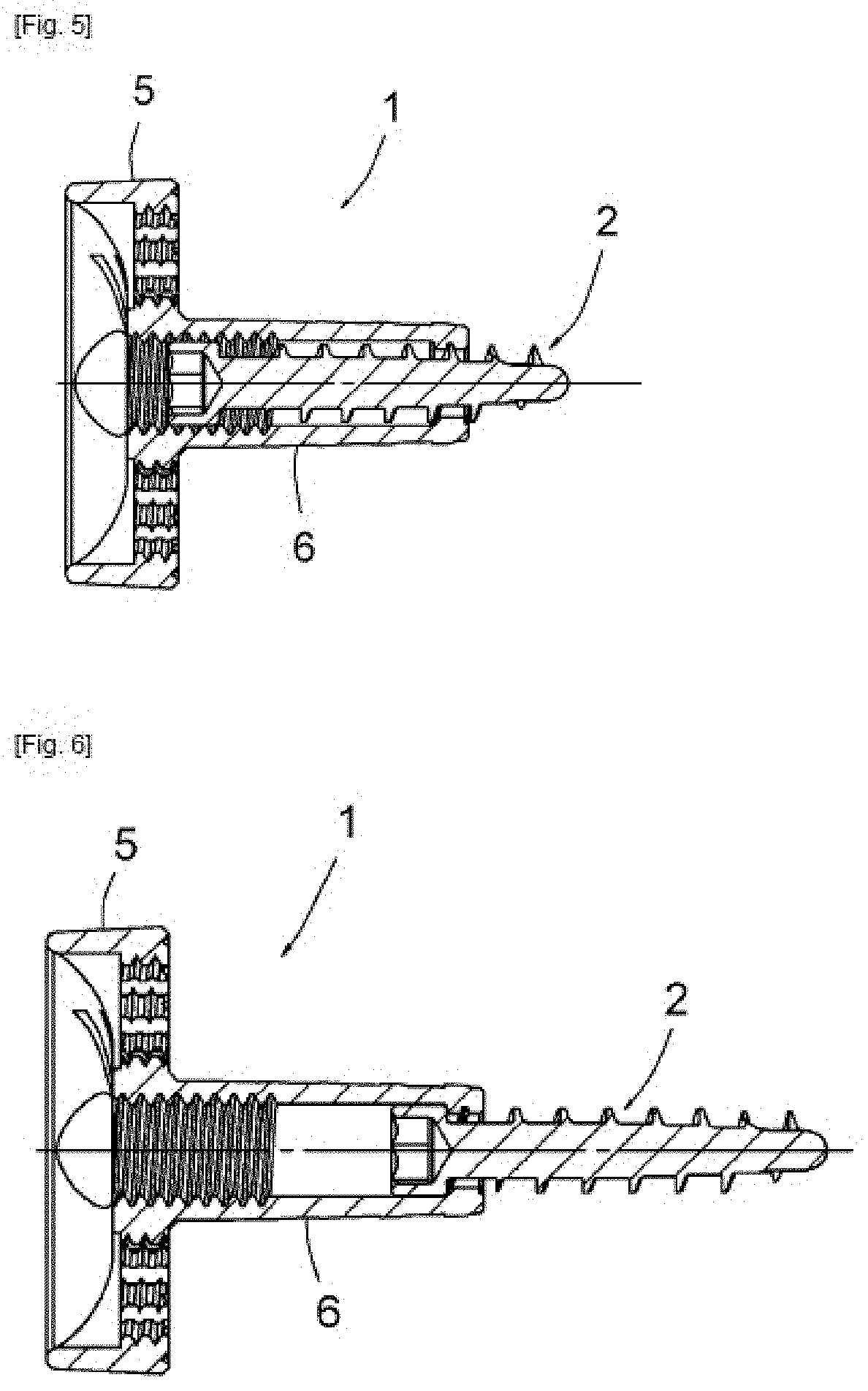
[0024]The figures show a glenoid base 1 of a prosthetic shoulder and a screw 2 intended to be screwed into the cancellous bone of a scapula in order to guarantee perfect anchoring of the base 1 to said scapula.

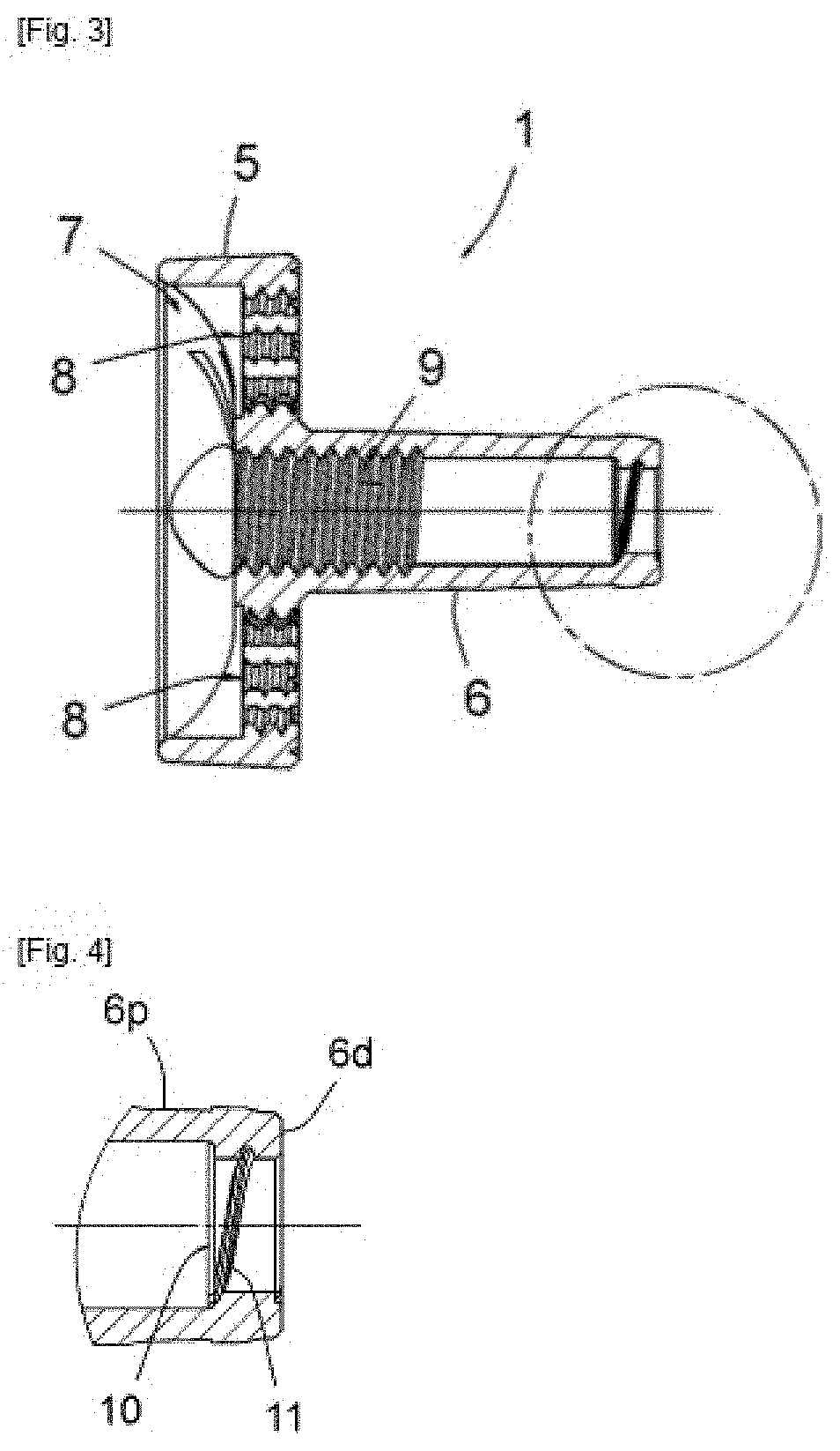
[0025]The base 1 comprises a plate 5 intended to receive an articular part (not shown) and a protrusion 6 of a piece with this plate, intended to be inserted tightly into a hole previously arranged in the cancellous bone of the scapula.

[0026]The plate 5 forms a proximal receiving housing 7, by force or with clipping, for said articular part, which may in particular be made from high-density polyethylene to guarantee sliding with the conjugated articular head of the part affixed to the end of the humerus.

[0027]In the illustrated example, the plate 5 comprises four holes 8 for receiving bone anchoring screws arranged through it, surrounding the protrusion 6. These holes 8 may be of the type described in French patent application No. FR 1,154,791 (U.S. Pat. No. 2,975,888), which ...


PUM


Abstract

An assembly has a bone anchoring base and a screw. The bone anchoring base has at least one protrusion configured to be inserted in a hole arranged in the cancellous portion of a bone. The screw has a thread suitable for engaging with the cancellous portion of the bone. The protrusion is inwardly hollow and comprises an orifice at its distal free end, the screw being configured to be engaged through the protrusion and screwed in the cancellous portion of the bone through the orifice. The orifice is tapped at the pitch of the thread of the screw and the thickness of a distal wall is such that it is possible to arrange more than half of a turn of the threading therein, suitable for receiving the thread of the screw, such that, during the placement of the screw, the thread of this screw engages with said distal wall.

Description

CROSS-REFERENCE TO RELATED APPLICATIONS[0001]This application claims priority under 35 U.S.C. § 119 to French patent application FR 1902535, filed Mar. 12, 2019, the disclosure of which is incorporated herein by reference in its entirety.TECHNICAL FIELD[0002]The present invention relates generally to a joint assembly, and, more particularly, to an assembly formed by a bone anchoring base belonging to a prosthetic joint and by at least one screw fastening this base to a bone.BACKGROUND[0003]A prosthetic joint frequently comprises two prosthetic parts fastened to the respective bones of the treated joint, at least one of these parts comprising a bone anchoring base and an articular part fastened to this base. The bone anchoring base frequently comprises at least one protrusion intended to be inserted into a hole arranged in the cancellous bone of the corresponding bone, in particular in the form of an anchoring stud. The base in question may in particular be a prosthetic shoulder glen...

Claims


Application Information

Patent Timeline
Patent Type & Authority Applications(United States)
IPC IPC(8): A61B17/86A61B17/68
CPCA61B17/864A61B17/685A61B17/86A61F2/4081A61F2/389A61F2/30749A61F2002/4085A61F2002/30878A61F2002/30822A61F2002/30827
Inventor MARTIN, BAPTISTEGLASER, DAVID LOUISSONG, FREDERICK SUHCOOK, ALFREDD'ONOFRIO, MARK
Owner FX SHOULDER USA INC
Why Eureka
Try Eureka