Spark plug

a technology of spark plugs and plugs, which is applied in the manufacture of spark plugs, spark plugs, electrical equipment, etc., can solve the problems of increasing the heat capacity of the spark plug, the difficulty of heat conduction through the enlarging portion toward the back, etc., and achieves sufficient kinetic energy, sufficient thermal energy, and the effect of increasing the gas flow in the front region of the enlarging portion

Active Publication Date:
View PDF0 Cites 1 Cited by
  • Summary
  • Abstract
  • Description
  • Claims
  • Application Information

AI Technical Summary

Benefits of technology

[0007]In addition, the cross-sectional area of the region surrounded by the enlarging portion along a plane perpendicular to the axial line decreases with increasing distance in the direction from back to front. Therefore, the speed of the gas flow in a front region of the enlarging portion can be increased. Accordingly, the jet flow injected into the combustion chamber has sufficient kinetic energy. Since the jet flow has sufficient thermal energy and sufficient kinetic energy, stable combustion of combustible air-fuel mixture can be achieved in the combustion chamber.
[0008]According to a spark plug of a second aspect, in the cross section including the axial line, a line showing an inner surface of the enlarging portion has a substantially constant radius of curvature. Accordingly, protrusions are not easily formed on the inner surface of the enlarging portion. As a result, overheating of the inner surface of the enlarging portion at the protrusions can be prevented. Thus, not only can the effects of the first aspect be obtained, but combustible air-fuel mixture that has flowed into the plug cap from the combustion chamber through the through holes can be prevented from undergoing pre-ignition with protrusions on the inner surface of the enlarging portion serving as ignition sources.
[0009]According to a spark plug of a third aspect, in the cross section including the axial line, the minimum distance from the outer surface to the inner surface of the plug cap is smallest at a front end of the inner surface of the plug cap. In this case, the heat capacity of a portion including the front end of the inner surface of the plug cap is less than the heat capacity of a portion including the front end of the enlarging portion. Accordingly, the temperature of the portion including the front end of the inner surface of the plug cap can be easily reduced. Thus, not only can the effects of the first and second aspects be obtained, but the combustible air-fuel mixture that has flowed into the plug cap from the combustion chamber through the through holes can be prevented from undergoing pre-ignition with the front end of the inner surface of the plug cap serving as an ignition source.
[0010]According to a spark plug of a fourth aspect, in the cross section including the axial line, the minimum distance from the outer surface to the inner surface of the plug cap is smallest at a front end of the outer surface of the plug cap. In this case, the heat capacity of the portion including the front end of the inner surface of the plug cap can be reduced in a region including the front end of the outer surface. Accordingly, the temperature of the portion including the front end of the outer surface of the plug cap can be easily reduced. Thus, not only can the effects of the third aspect be obtained, but the combustible air-fuel mixture in the combustion chamber can be prevented from undergoing pre-ignition with the front end of the outer surface of the plug cap serving as an ignition source.
[0011]According to a spark plug of a fifth aspect, a front end of the outer surface of the plug cap is a flat surface. In this case, overheating of the front end of the outer surface of the plug cap can be reduced. Therefore, not only can the effects of the first to fourth aspects be obtained, but the combustible air-fuel mixture in the combustion chamber can be prevented from undergoing pre-ignition with the front end of the outer surface of the plug cap serving as an ignition source.
[0012]According to a spark plug of a sixth aspect, the plug cap includes a straight portion formed between the enlarging portion and back ends of the plurality of through holes. A cross-sectional area of a region surrounded by the straight portion along a plane perpendicular to the axial line is constant over entire length of the straight portion in a direction of the axial line. Accordingly, the gas flow can be accelerated with less loss in the gas flow in the straight portion. Since the jet flow injected into the combustion chamber has sufficient kinetic energy, not only can the effects of the first to fifth aspects be obtained, but stable combustion of the combustible air-fuel mixture can be achieved in the combustion chamber.

Problems solved by technology

Heat conduction through the enlarging portion toward the back becomes more difficult with increasing distance in the direction from front to back, and heat capacity of the enlarging portion increases with increasing distance in the direction from back to front.

Method used


Image

  • Spark plug
  • Spark plug
  • Spark plug

Examples


first embodiment

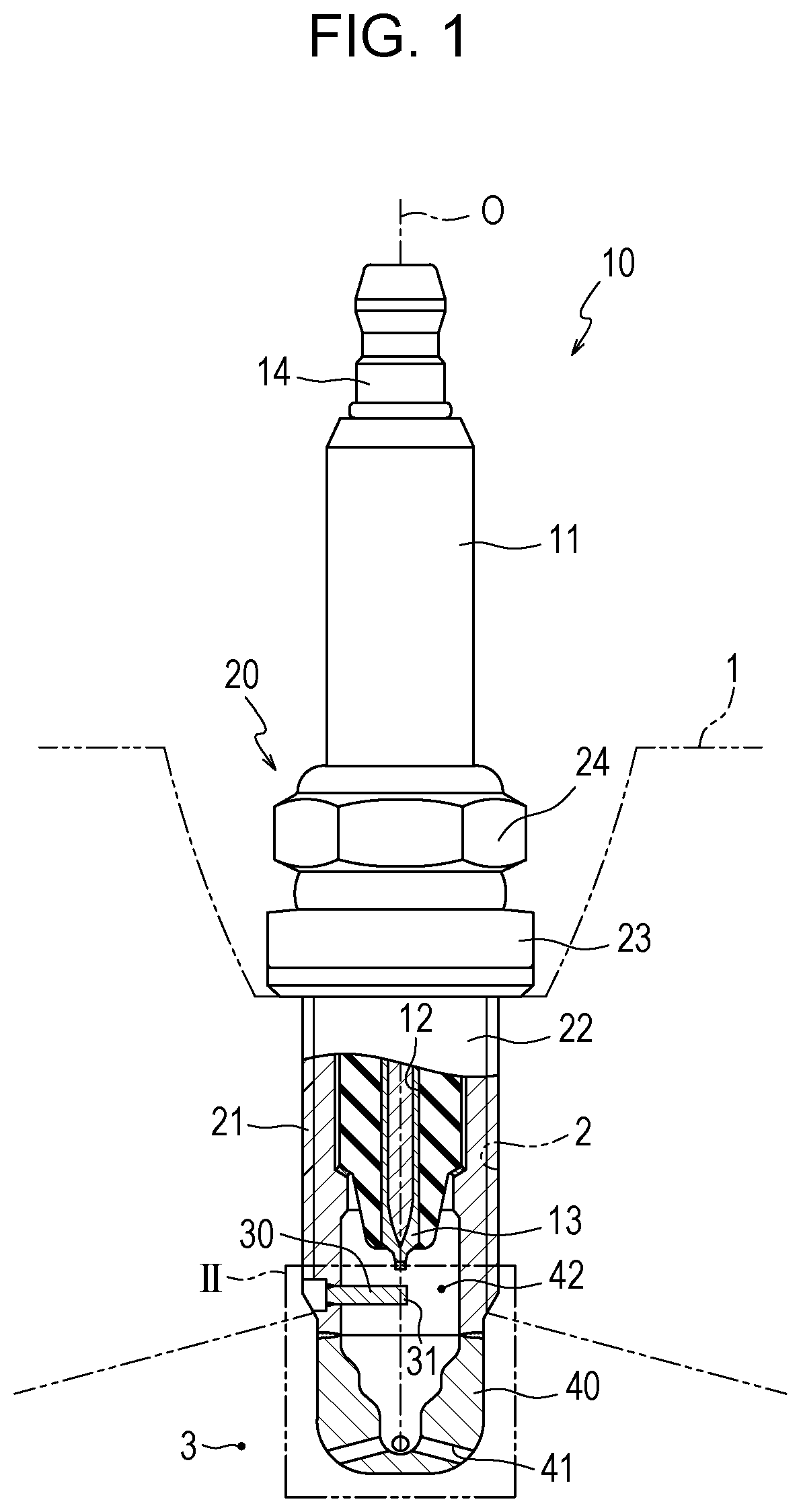
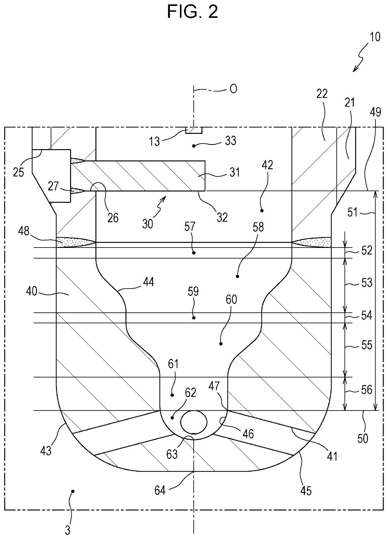
[0018]Preferred embodiments of the present invention will now be described with reference to the accompanying drawings. FIG. 1 is a partially sectioned view of a spark plug 10 according to a The bottom of FIG. 1 is defined as the front of the spark plug 10, and the top of FIG. 1 is defined as the back of the spark plug 10. This also applies to FIGS. 2 to 5. FIG. 1 shows a cross section of a front end portion of the spark plug 10 including an axial line O. As illustrated in FIG. 1, the spark plug 10 includes an insulator 11, a center electrode 13, a metal shell 20, a ground electrode 30, and a plug cap 40.

[0019]The insulator 11 is a substantially cylindrical member having an axial hole 12 that extends along the axial line O, and is made of a ceramic, such as alumina, having good mechanical characteristics and high insulation properties at high temperatures. The center electrode 13 is disposed in a front region of the axial hole 12 in the insulator 11. The center electrode 13 is elec...

fourth embodiment

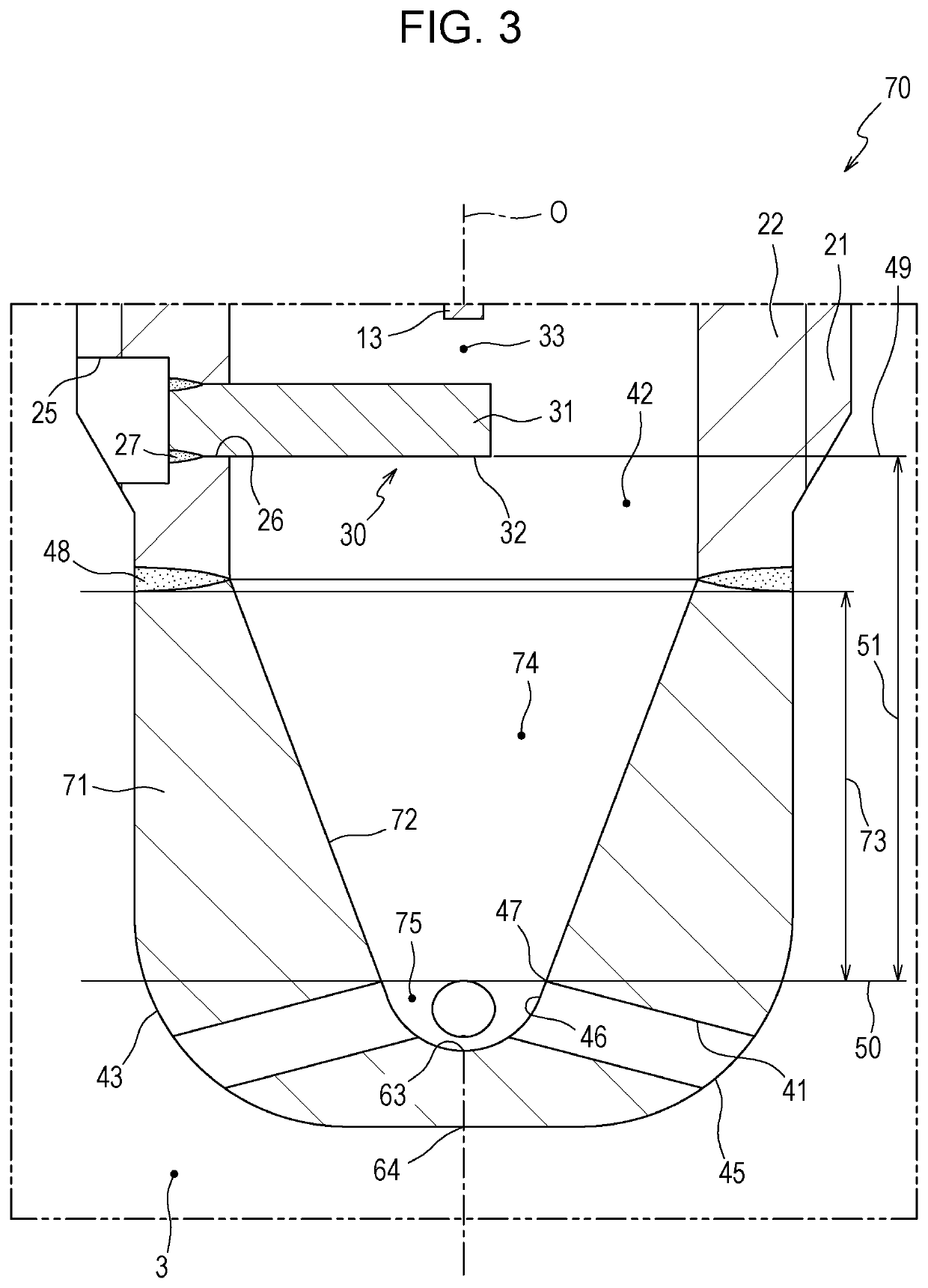
[0062]In the fourth embodiment, the lines showing the inner surface 92 of the enlarging portion 105 in a cross section including the axial line O include radially inwardly convex inflection points. However, the enlarging portion 105 is not necessarily limited to this. For example, the lines showing the inner surface 92 of the enlarging portion 105 may, of course, have radially outwardly convex inflection points at positions behind the radially inwardly convex inflection points. Also in other embodiments, the inner surfaces of the enlarging portions may, of course, have radially outwardly convex inflection points.

[0063]Each embodiment may be modified by providing one or more portions of the structures of other embodiments in addition to the structure thereof or in place of one or more portions of the structure thereof or by omitting a portion of the structure thereof.

[0064]For example, in the first embodiment, the first straight portion 52 may, of course, be omitted and the first enl...


PUM


Abstract

A spark plug includes a plug cap having a plurality of through holes. In a cross section including an axial line, the plug cap includes an enlarging portion in a portion of a region between a first imaginary straight line and a second imaginary straight line, the first imaginary straight line extending through a front end of the end portion of a ground electrode and being perpendicular to the axial line, the second imaginary straight line extending through a back end of one of inner open ends of the through holes that is closest to a front end of the spark plug and being perpendicular to the axial line. The enlarging portion being a portion in which a minimum distance from an outer surface to an inner surface of the plug cap increases with increasing distance in a direction from back to front.

Description

FIELD OF THE INVENTION[0001]The present invention relates to a spark plug including a pre-chamber for a combustion chamber of an engine.BACKGROUND OF THE INVENTION[0002]A spark plug including a pre-chamber for a combustion chamber of an engine is known. For example, see Japanese Unexamined Patent Application Publication No. 2017-103179 (“PTL 1”). This type of spark plug includes a plug cap that has through holes and that is connected to a front end portion of a metal shell. The spark plug ignites combustible air-fuel mixture that has flowed into the plug cap from the combustion chamber through the through holes. The air-fuel mixture is combusted to generate an expansion pressure that causes a gas flow including flame to be injected into the combustion chamber through the through holes, so that the combustible air-fuel mixture in the combustion chamber is rapidly combusted due to the injected jet flow.[0003]According to the technology described in PTL 1, the plug cap has a substantia...

Claims


Application Information

Patent Timeline
Patent Type & Authority Applications(United States)
IPC IPC(8): H01T13/32H01T13/39H01T13/06H01T21/02
CPCH01T21/02H01T13/06H01T13/32H01T13/39H01T13/54H01T13/16
Inventor BAN, KENJIGOZAWA, TATSUYA
Why Eureka
Try Eureka